News Article
Speeding up silicon with infrared lasers
Growth of laser structures on silicon chips promises to overcome a looming bottleneck in data transfer

BY HIMANSHU KATARIA AND SEBASTIAN LOURDUDOSS FROM KTH-ROYAL INSTITUTE OF TECHNOLOGY
The ways that we spend our free time have changed. While many of us still watch TV, read books and listening to the radio, over the last decade or so we have also started to surf the web, watch films over internet and stream our music.
This relatively new opportunity for so much choice at the click of a button is great, but it comes at a price: Ever-growing levels of data transfer are putting increasing strain on the internet backbone, and the CMOS-based electronics that is used to upload, download and transfer this data is running out of steam.
What is the cause of this impending bottleneck? Well, it is not due to the processing speed of the microprocessor. Instead, it is associated with the speed of data transfer between the chips. This is limited by the copper wires that connect them.
A hike in data transfer rates is possible by replacing the wire with tracks in silicon that can route light from one chip to another, and direct it around the chip. However, this silicon-photonics approach is hampered by the lack of an efficient silicon laser, so one made from III-Vs has to be employed "“ and the integration of this is challenging.
One way to unite a laser with a silicon chip is to bond the two together. This is quite easy to do, but it does not guarantee great performance, due to the silicon-on-insulator wafers used in the process. The insulating layer sandwiched between the silicon is a low-thermal-conductivity dielectric that hampers the dissipation of heat generated by the laser, leading to device heating and reduced performance. What's more, bonding chips together can compromise yield. To bring the laser onto the silicon chip, either III-V dies or a wafer must be selectively bonded to a larger silicon substrate. This can lead to unacceptable variations in the thickness of the intermediate bonding layer across the silicon. Although chip-to-chip bonding can address this, it is expensive, and stringent alignment requirements can impact yield.
Monolithic integration
A far better way to unite a microprocessor chip with a III-V laser is via monolithic integration. This is the approach that has been adopted by several groups across the world, including ours at KTH in Sweden, where we have developed a novel approach for creating defect-free layers of InP.
The biggest challenge with all epitaxial approaches to integration is to combat the large differences in lattice and thermal expansion coefficient. This can lead to III-V materials that are riddled with defects, which can act as charge trapping sites that reduce carrier lifetimes and ultimately kill the device. To prevent this from happening, we employ a method known as epitaxial lateral overgrowth (ELOG), which involves selective growth of a defect-free layer of InP in openings defined in a thin film of dielectric deposited on silicon (see Figure 1).

Figure 1: Epitaxial layer overgrowth holds the key to forming defect-free InP on silicon.
With this approach, defects generated at the interface between the III-V and silicon are filtered by the dielectric film, enabling the deposition of a defect-free InP layer that can act as a virtual substrate for selective growth of InGaAsP-based multi-quantum wells. Armed with this technology, the door has been opened to the creation of truly monolithic integrated photonic circuits on silicon, which up until now have only been possible with bonding approaches.

The HVPE reactor at KTH has been used to form InP layers on silicon substrates with SiO2 stripes.
Creation of the high-quality InP that is essential for adding a laser is based on selective-area growth via HVPE, employing near-equilibrium conditions. The first step involves deposition of a thin InP layer on silicon to create a seeded substrate. After this, a film of the dielectric SiO2 is deposited and subsequently patterned using lithographic techniques to create a series of SiO2 stripes across the wafer. This leaves us with a region of exposed InP that is riddled with defects. On further growth of InP these defects can climb, but what is interesting "“ and critically important "“ is that they follow a specific angle associated with a crystal plane. What this means is that if the ratio of the thickness of the opening to the height of this trench is chosen carefully, defects can annihilate at the walls, and therefore block defects not only beneath the mask, but also within the opening.
By carrying out a series of experiments, we have optimised the growth of coalesced ELOG InP in ten openings that are 300 nm across and spaced 1 µm apart. This has led to the formation of templates with a smooth ELOG InP layer that has an overall width of around 15 µm.
We have used these templates as a foundation for the MOCVD growth of InGaAsP-based multi-quantum well structures emitting at 1.55 µm. Forming such structures has not been easy, due to loading effects selective growth can result in thicknesses and composition of the wells and barriers being far different from those on a planar substrate. However, after conducting many experiments, we have refined the dielectric mask pattern so that the loading effect is reduced during MOCVD growth.

Figure 2: Atomic force microscopy reveals the high degree of flatness of coalesced ELOG InP on silicon.
Atomic force microscopy reveals the smooth epitaxial surface after multi-quantum-well growth (see Figure 2). However, this active region is by no means perfect, and there is inhomogeneity in the thicknesses of the multi-quantum wells, according to images provided by transmission electron microscopy (see Figure 3). It is possible that this is caused by the tremendous loading effect during selective growth of multi-quantum wells on a very small area. However, it might also result from unevenness caused by the coalescence of parallel growth fronts during ELOG.

Figure 3: Cross-sectional transmission electron microscopy reveals the variations in thickness in individual layers within the InGaAsP multi-quantum wells that are formed on coalesced ELOG InP on silicon.
Growth of a polar material onto a non-polar layer "“ such as the growth of InP on silicon "“ can create anti-phase domains, which are formed when bonds between identical atoms occur along particular directions. These domains can be eradicated by turning to growth on off-orientated substrates, but even this step may not prevent new defects arising. That's because imperfections can also appear at the coalescent junction between two parallel growth fronts, and form due to the interaction of an epitaxial layer with the dielectric thin film. So, in order to achieve a defect-free epitaxial layer all over the dielectric mask, it is essential to avoid coalescence of parallel growth fronts and obtain a dielectric film with a smooth surface and sidewalls.
Thanks to these insights, we have formulated our experiments in such a way that we have been able to grow almost-defect-free, isolated large areas of ELOG InP on silicon (see Figure 4). These un-coalesced stripes of InP were formed via growth in 1 mm-wide openings separated by 20 µm. The openings were defined by conventional optical lithography a common workhorse in the present day photonic industries and covered a square area with sides of 12.5 mm. Note, however, that there is no reason why this process cannot be scaled to enable the growth of InP regions over large wafers.

Figure 4: Turning to a new ELOG process led to the formation of un-coalesced large areas of InP on silicon.
Although the stripes of SiO2 are far more isolated than before, an ELOG approach can still be applied. This is what we have done, fine-tuning our process to avoid the coalescence of parallel growth fronts. Defect blocking still takes place, despite such a wide opening, according to cross-sectional transmission electron microscopy of a lamella taken from a sample (see Figure 5).

Figure 5: Cross-sectional transmission electron microscopy reveals the defect-filtering mechanism in wide openings.
We have used these templates as virtual substrates for MOCVD growth of InGaAsP multi-quantum wells emitting at 1.55 µm. Our previous efforts provided us with the approaches to reduce loading effects during the growth, and this has ultimately enabled us to form a high-quality, highly uniform active region with clean interfaces across the whole layer (see Figure 6). We believe that this high level of uniformity in the quantum wells is also due to the relatively large area of InP available, which is sufficient for broad area laser fabrication. Encouragingly, the photoluminescence produced by these samples is comparable to that emitted by a control sample, which was grown at the same time on planar InP.

Figure 6: Transmission electron microscopy shows the high quality of the InGaAsP multi-quantum wells grown on uncoalesced ELOG InP on silicon.
Keeping cool
By having InP beneath the laser, rather than an intermediate bonding layer, the surrounding region is far better at sucking heat out of the device and preventing it from over-heating. Interestingly, simulations by our team have shown that the wider the opening in SiO2, the better the thermal conductivity, so we have tried to use this in our templates. This has led us to optimise the deposition process for structures with 1 µm-wide openings in SiO2 that are etched to a depth of 2 µm. By optimising our growth process, we can realise complete defect filtering with these processed wafers, while maintaining a smooth SiO2 surface and sidewalls to avoid generation of any new defects.
Getting the light in
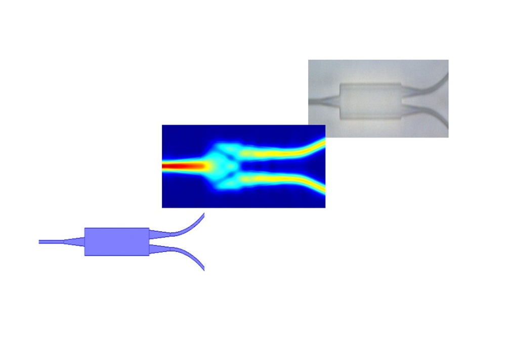
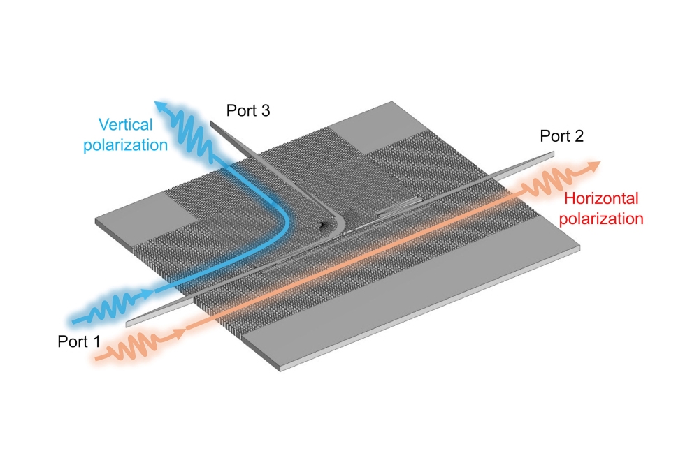
Integration of III-Vs and silicon requires coupling of the generated optical mode in the active region to the underlying silicon. To do this, there must be evanescent coupling of the optical mode with the silicon waveguide, which is buried in the dielectric mask in such a way that the whole structure works not only as a defect filter but also as a platform for evanescent coupling of the optical mode.
Simulations by us, and also by the group of Pallab Bhattacharya from the University of Michigan, show that evanescent coupling can occur between InGaAs/GaAs based quantum dot lasers and a lab-grown silicon-SiO2 waveguide-cladding structure with similar dimensions. We are still to fabricate final devices using our ELOG technology. However, we don't anticipate any major obstacles to realising this, given the excellent material quality of the isolated large areas of InP, and the subsequent growth of uniform InGaAsP multiple-quantum wells.
One of the challenges that still lies ahead is that the photonic industries continues to live in the micro world, and substantial scaling is therefore required, given that the electronics industry has reached the smallest possible nano-dimensions.
Other groups have started to try and close this gap by either developing tiny plasmonic-based devices or ultra-small cavity lasers based on GaAs nanowires and InP polytypic nanorods "“ the latter feature ultra-low thresholds.
Our integration scheme may help in all these efforts, because it promises to deliver an affordable, monolithically integrated platform for III-Vs and silicon that can form the foundation for the highly complex photonic integrated circuits needed in the near future.
Several co-workers in our laboratory contributed to this work. This work was partially supported by URO of Intel Inc., US, in which we enjoyed the fruitful collaboration with John Bowers from UCSB.
Further reading
H. Kataria et. al. Semicond. Sci. Technol. 28 094008 (2013)
H. Kataria et. al. IEEE J. Sel. Top. Quant. Electron. 20 JULY/AUGUST (2014)
H. Kataria et. al. Proc. of SPIE 8989 898904-1.
Z. Wang et. al. Materials Science and Engineering B 177 1551 (2012)
J. Wang et. al. Opt Exp. 16 5136 (2008)