Technical Insight
Turbocharging VCSELs
How can we accelerate VCSELs to the speeds needed in chip-to-chip optical interconnects? Add a little strain to the quantum wells, tune the photon lifetime and trim cavity size and oxide capacitance, suggest Chuan Xie, Neinyi Li, Phillip Brow and Kenneth Jackson from Sumitomo Electric Device Innovations.
The VCSEL has many great attributes for providing the light source in fibre-optic data communication. It has a beam profile that is relatively easy to couple into a fibre; it can be cheap to produce; it enables on-wafer testing; it consumes very little power; and it can now be switched on and off at very high speeds, enabling rapid data transfer.

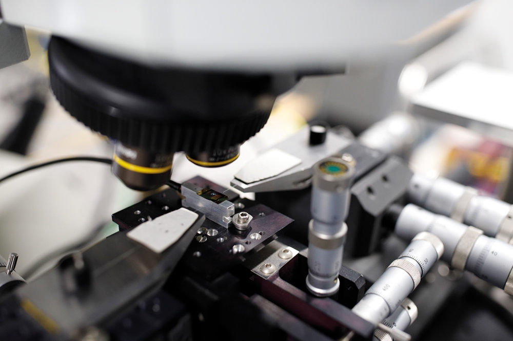
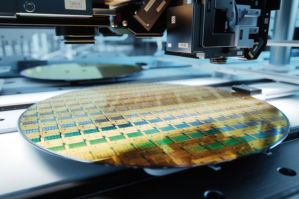
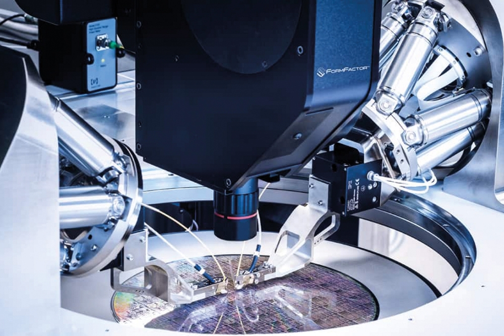
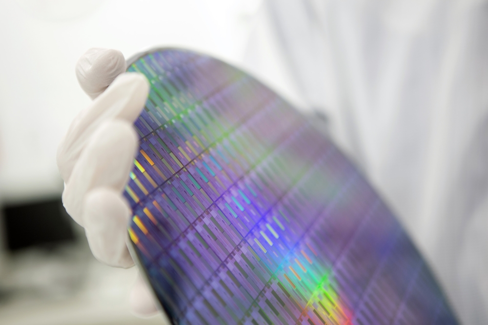
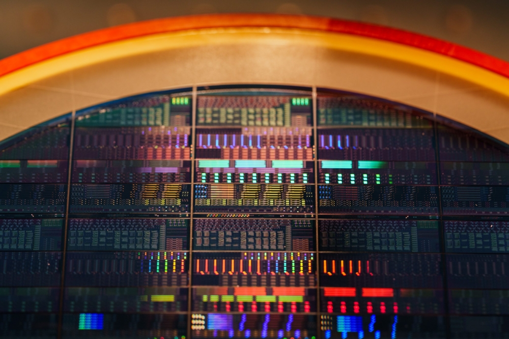
One of the strength’s of VCSELs is they allow on-wafer chip testing
Since making its debut more than 30 years’ ago, the maximum modulation speed of the VCSEL has crept up and up from a starting point of about a gigahertz. A couple of years’ ago a 25 Gbit/s represented state-of-the-art performance in a research lab and VCSELs operating at these speeds will soon be launched onto the market. Initially these products will conform to standards such as Fibre Channel 32GFC and Infiniband EDR, and they will be employed in short data links, such as those used to link up scores of PCs and servers in offices. However, this should be followed by more interesting, technologically disruptive applications such as the long awaited chip-to-chip optical interconnects and optical back planes. Operating at such high data rates, photons will emerge as the indisputable winners of the ‘photon-versus-electron race’.
VCSELs can cover a wide range of wavelengths. However, the most common, commercially successful designs use mirrors built from the pairing of AlGaAs of different aluminium mole fractions and they feature GaAs quantum wells emitting at 850 nm to match one of optical fibre’s transmission windows. This type of VCSEL has been a workhorse in data-communications for more than 15 years.
Rewind the clock to the 1990s, a time when the required data rates for short-reach communications were below 5 Gbit/s, and the 850 nm VCSEL was ‘naturally’ fast. However, when data rate rose to 10 Gbit/s, this device started running into difficulties. For nearly a decade, the data rate of commercial VCSELs lingered at around 10 Gbit/s, and it was difficult to foresee how this could be doubled. But it has. Although it’s not been easy to do this, several VCSEL manufacturers have developed devices that can go this fast.
One of them is our team at Sumitomo Electric Device Innovations USA in Albuquerque, New Mexico. Our group has a strong track record in manufacturing high-quality VCSELs for data communications. For example, thanks to recent performance and reliability improvements to our 10 Gbit/s VCSEL, the Ultralase, we have been the leading provider for several standards of active optical cables.
Our efforts at developing 25 Gbit/s VCSELs started just over 18 months ago, and our design is now in the advanced stage, with prototypes producing respectable performance. To reach these very high speeds we have had to develop devices with a very high bandwidth. In designs such as the Ultralase, bandwidth saturates at around 10 to 11 GHz at high temperature, which is more than enough for operation at 10 Gbit/s, and sufficient for even 14 Git/s (see Fig. 1(a)). But to operate at 25 Gbit/s, we need a minimum bandwidth of 16-18 GHz – drastically higher than the current device capability. Bridging this gap is the biggest challenge to making really high speed VCSELs.

Fig. 1. Sumitomo’s successor to its 10 Gbit/s VCSEL is designed to operate at 25 Gbit/s and has a superior 3 dB bandwidth at 25°C and 85°C (a). The slope of curves of relaxation oscillation frequency (ROF) as a function of bias indicate how fast bandwidth ramps with bias (b)
Back to basics
To understand the limits to reaching higher speeds, you have to understand some of the basic operating principles of a VCSEL. Like every class of semiconductor laser, this device reaches its threshold – the point at which it starts to emit laser light – when the carrier density in the gain medium hits a level where gain fully compensates for cavity loss. Increasing the drive current further causes light output to rise linearly with injection current for relatively low bias current.
Crank up the current to higher values and the device enters a new regime: Light output increases with current in a sub-linear manner, and eventually rolls over at increased bias. This rollover results from a rise in junction temperature due to self-heating – that’s why it is often referred to as ‘thermal rollover’.
At a higher junction temperature, maintaining the same gain requires more carriers, so an increasing fraction of the injection current is consumed to balance the loss, lowering the light emission efficiency. When the increase in current can no longer make up for the increase in threshold, the laser power starts to drop.
Self-heating severely limits the performance of VCSELs, due to their intrinsic high-current density and large thermal impedance, which stems from a far smaller size compared with edge-emitting cousins. This heating not only hampers the device’s efficiency to produce light – it lowers its speed. In a directly modulated laser, gain governs the modulation of light. If the laser is to respond rapidly to the modulating current, gain must change sharply in response to adjustments in carrier density.
The rate that gain changes with carrier density is called the differential gain, and it must be high to ensure high-speed operation. Unfortunately, gain rises sub-linearly with carrier density and it decreases with rising temperature, so a high junction temperature lowers differential gain. The upshot is that bandwidth, like output power, is a victim of thermal rollover.
A significant downside of the VCSEL is that its thermal impedance cannot be made arbitrarily low to overcome the thermal limitation. Techniques that are well known for trimming thermal impedance, such as using binary material rather than ternary and quaternary alloys wherever possible, have already been incorporated in most 10 Gbit/s designs. Any further improvements in this area are limited, and may not be easy to implement.
Given that it is very difficult to push out the onset of thermal rollover, increases in bandwidth must come below the thermal limit. Such a design will be welcomed by many, because a faster device that consumes no more power than existing products will be highly valued in many applications. But how is it possible to make a VCSEL with a bandwidth that ramps up faster with bias current?
One approach is to reduce the optical mode volume, because this increases the photon density. An obvious way to realise this is to trim the aperture size, but this is not a great idea because smaller apertures increase current density and aggravate thermal bottleneck. Another option is to cut the cavity length, but there isn’t much headroom here, because the cavity in 10 Gbit/s designs is only one wavelength long. Further shortening is possible, but the gain is not sufficient in itself to spur VCSEL speeds to 25 Gbit/s.
New active regions
Far greater gains are promised by selecting a better gain medium. Until now, active layers of commercial VCSELs have sandwiched GaAs quantum wells (QWs) with AlGaAs barriers. This design is easy to manufacture and has proven reliability, but to make the leap to 25 Gbit/s and beyond, the industry will have to abandon this traditional approach.
Our new design employs compressively strained QWs for higher differential gain, while maintaining an emission wavelength of 850 nm. Materials for both the QWs and the barriers have been carefully chosen to produce an ideal level of strain, and the growth conditions optimized for performance and reliability. The number of quantum wells are chosen to maximise differential gain, and this judicious selection, plus the composition of the active region, promises to double differential gain.
When one roadblock to higher speeds is removed to any class of device, there is always the threat that another takes its place. With VCSELs, the danger is that parasitic elements become the new bandwidth bottleneck, but it is possible to prevent this from happening by minimizing pad capacitance (see Figure 2 for the VCSEL’s parasitic equivalent circuit). This has already been reduced to negligible levels in our 10 Gbit/s design and it has now become necessary to lower the oxide capacitance, so that less high-frequency modulation is shunted by it. Reducing parastic elements, in particular the oxide capacitance, has a significant impact on the frequency response of the laser (see Figure 3). Cutting oxide capacitance in half is one of the goals for our 25 Gbit/s design.

Fig. 2. A circuit diagram for the VCSEL’s parasitic equivalent circuit.Cp is pad capacitance; Li is inductance of interconnect metal; Rm is resistance from mirror stack; Ca is aperture capacitance; Ra is aperture resistance

Fig. 3. Reducing device parasitic elements, such as oxide capacitance, enables VCSELs to realise higher modulation speeds
More than a bandwidth game
If you read through the theory section of textbooks detailing laser behaviour, somewhere you’ll likely to find a prediction for where the maximum bandwidth occurs – at the point where the relaxation oscillation is critically damped. According to theory, our current 10 Gbit/s VCSEL should reach an ultimate bandwidth of 22 to 27 GHz. In reality, however, it is less than half of this, due to thermal rollover.
A major term that defines the maximum bandwidth is inversely proportional to photon lifetime. This has led many engineers within the optoelectronic industry to believe that one of the best handles for increasing the bandwidth is cutting photon lifetime. But this is a misconception, at least for the VCSEL.
Cut photon lifetime and you get an unwanted side effect – reduced damping of the relaxation oscillation under the actual operation bias. This is limited by the thermal effect and requirements for either power consumption or reliability, or both of them. The key point to note is that insufficient damping degrades signal integrity, which can be seen as overshoot and jitter in the optical eye diagram. Making matters worse, a shorter photon lifetime increases cavity loss, leading to a higher threshold. In turn, this lowers the differential gain that we have tried so hard to maximize.
In our view, the correct approach is to select a photon lifetime that is sufficiently short to not unduly penalize the bandwidth, but long enough to offer low threshold and ample damping. The good news for us is that our simulations show that the photon lifetime of our 10 Gbit/s design is also a good choice for 25 Gbit/s (see Figure 4 for details).

Fig. 4. Simulations show that changes to photon lifetime impact the laser’s frequency response. The bandwidth decreases with increasing photon lifetime, and so does the amount of peaking. Eye diagram simulations (Fig. 4. (b) to (d)) reveal that when peaking is high (low damping), overshoot and jitter are more severe. However,when photon life is too long, rise and fall times begin to increase and the eye starts to close vertically
Putting theory to the test
Based on the design strategy just detailed, we have carried out extensive simulations to narrow the range of design parameters. Since there is some uncertainty in many material characteristics, there is some trial-and-error associated with the process of designing, building, evaluating and modifying our lasers. However, we have found that after a few iterations, our device’s performance is now close to its target. The improved bandwidth characteristics compared to our 10 Gbit/s design are shown in Figure 1, and eye diagrams for the 25 Gbit/s laser are shown in Figure 5. The focus has been on the laser’s intrinsic parameters; there is still room to increase the parasitic bandwidth of our device, so better performance is expected in the final design.

Fig. 5. Increasing the 25 Gbit/s operating temperature from 25°C (a) to 85°C (b) leads to a slightly inferior optical eye diagram
Our lasers could have a big role to play in the growth of deployment of optical interconnects, which have been touted for many years as the next technological breakthrough. Many believe that there will come a time when various electrical interconnects are replaced by those operating in the optical domain because data rates will become too high for copper to handle effectively. It may be that the optical interconnects within an integrated circuit will have to wait for ‘silicon photonics’ to yield an efficient, more mature light source that is readily implemented on silicon.
However, for optical interconnects between ICs and among line cards, nothing can surpass the VCSEL as the premier light source. It wins thanks to its small size, its high efficiency that translates into low power consumption, its low manufacturing cost, and because it is readily made into one- or two-dimensional arrays flip-chip mountable on silicon, IC carriers, and PCBs alike. Now that the VCSEL has finally approached the critical data rate for optics to dislodge copper, the ‘flood gate’ is opening.
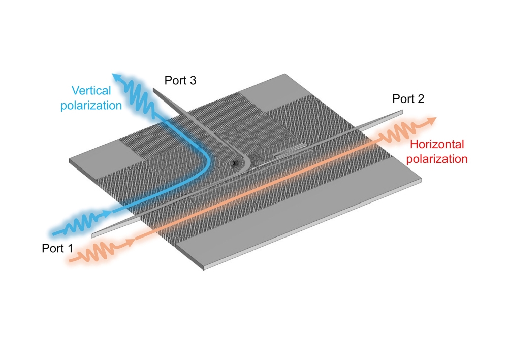
To our delight, even before we can put the finishing touches to our new device, many researchers have been getting in touch and asking us if they can try this VCSEL in their new interconnect transceivers. We have fulfilled some of these wishes, and our VCSELs, plus corresponding photodetectors, have been grouped together to provide data transmission down novel multicore fibres (see Figure 6) and used to build a four-channel receiver (see Figure 7).

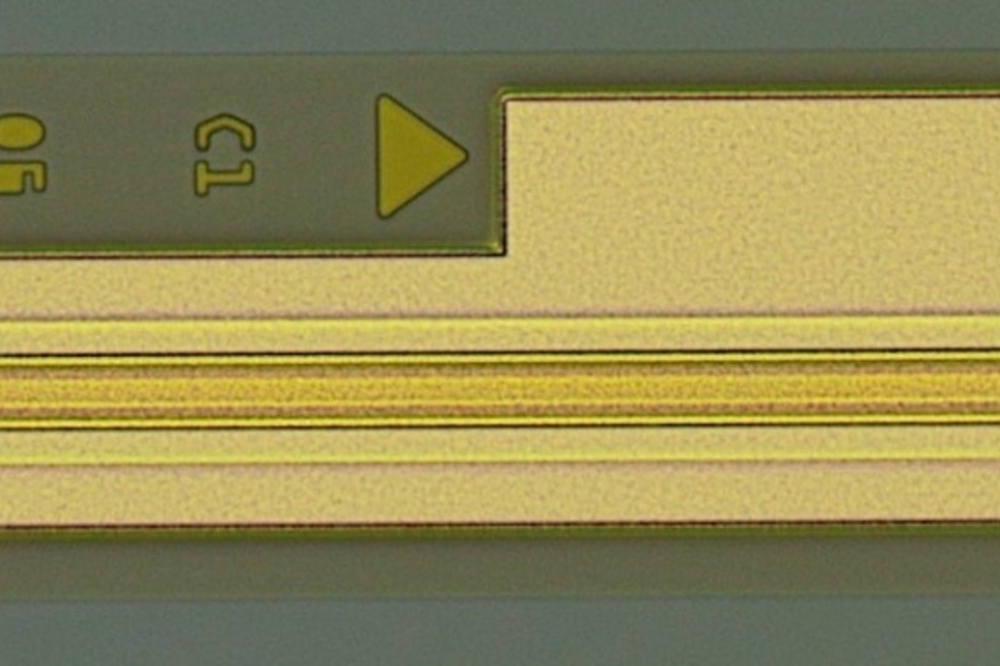
Fig. 6. (a) Transceiver schematic and (b) selected images showing the VCSEL and photodiode arrays viewed through the silicon carrier’s optical vias from the underside of the package
Have we now reached the limit of what is possible? Or can data rates go even higher, to 35 Gbit/s, 40 Gbit/s, or even 50 Gbit/s? In our view they can, but it will be about revolution, rather than evolution. It will require some help from the driver, such as pre-emphasis, and the introduction of new modulation schemes with higher bandwidth efficiency.

Fig. 7. A 4 x 25 Gbit/s transceiver made with precursory version of 25 Gbit/s VCSELs (see www.fujitsu.com/global/news/pr/archives/month/ 2012/20120531-01.html for more details)
Implementing these technologies may be tricky, but there doesn’t seem to be an insurmountable barrier to ultra-fast optical interconnects. That’s good news, because their electrical equivalents are clearly running out of steam.
The authors would like to thank Fuad Doany, Dan Kuchta, Ben Lee, and Clint Schow from IBM Thomas J. Watson Research Center for their collaboration and feedback. Our gratitude also goes to Chun Lei from Emcore Corp. for her instrumental contributions to our VCSEL program in the past few years. Many thanks go to the excellent team of the Albuquerque VCSEL FAB who made everything happen.
Further reading
N Li et al. 2012 Proc. SPIE 8276 827603 A V Rylyakov et al. 2012 OFC 2012, Los Angeles, CA OTh1E.1 B G Lee et al. 2012 J. Lightwave Tech. 30 886 L A Coldren et al. Diode Lasers and Photonic Integrated Circuits, Chapter 5, John Wiley & Sons 1995