Photonic Integration: What is the Holy Grail?
If photonic integration had come first, the metrics would be different…but it didn’t. Electronics integration at the semiconductor level came first, and the silicon electronics industry set in stone the expectations of integration through vehicles such as Moore’s Law. Tracking the number of transistors that comprise a microprocessor over the last three decades is a metric that the electronics industry takes seriously… and it has achieved a level of success beyond what anyone would have imagined even twenty years ago. So why would it have been different if photonic integration had come first? Simply, integrating photonics functions is different. Photonic integration is typically specific to each application.

This implies that different photonic devices need to be integrated. On a general level, photonics is still at the analog stage while electronics, which utilizes analog transistor devices, actually uses them in a digital format. The digital format allows high levels of integration. Photonics has yet to achieve this digitized level of integration, and is currently in the analog domain. The Holy Grail for photonic integration is digitization.
The challenge is to predict when this will occur. We will need a strong application in the marketplace, but to ensure success, we might well need standardization and process equilibrium: the consolidation of different device structures to a few (rather like p-MOS, n-MOS to CMOS— complementary metal-oxide semiconductor— in the electronic semiconductor industry). A review and synopsis of photonic integration over the last 30 years is shown in Figure 1. Photonic integration must utilize foundry-based technology in order to move past the analog regime into a digital regime. This will require common fabrication processes, devices, and technology, something that is almost heresy in the photonics world.
It is popularly observed that the photonic industry actually survives on differentiation in device design and process in order to show superior performance. With hundreds of semiconductor laser designs that emit at 1550 nm or even 1310 nm, when will the industry agree on a common platform?When will the industry agree on a DFB laser that, for example, accomplishes 80% of the specifications needed on most telecom systems equipment?
Digitization is the agreement on common platforms. Digitization is the Holy Grail for photonic integration. Digitization must occur for photonic integration to become an accepted technology platform for broad product applications. When will the photonics industry see analog functions architecturally in a digitized format?
2.0 Photonic Integration: Introduction and definition
Photonic integration typically means the integration many different types of optical components such as lasers, modulators, detectors, multiplexers, optical amplifiers, etc. It can be monolithic or hybrid, and there are many varieties and options. The majority of solutions have resorted to hybrid approaches, rather than the traditional monolithic approach. Monolithic approaches both electronic and photonic devices are considered. In fact, over the last two decades, the original term optoelectronic integrated circuit (OEIC) has been superseded by the term photonic integrated circuit (PIC). PICs today do not incorporate electronics; when they do, the term may evolve to a different acronym.
The traditional definitions for photonic integration are noted below, followed by newer definitions as the industry is beginning to adopt a more organized approach with A-PICs, OE-PICs, etc.
3.0: Drivers for photonic integration
Technology, whose development is to be pursued for commercial rather than scientific reasons, should enable tangible economic and technological benefits. This is certainly the case for PICs, which promise important benefits across a wide range of attributes. At the simplest level, the case for PICs parallels that for silicon ICs: the ability to monolithically integrate many distinct devices and functions onto a common chip vs. using many discrete components, thereby delivering important gains in packaging efficiency, smaller size and lower power use, increased reliability, and very importantly, lower cost per device. It has been continually argued, however, that the benefits of PICs go beyond simple densification and cost reduction; they enable increased functionality.
This increased functionality drives end-user value by enabling the addition of cost-effective functions that would otherwise not be economically viable, or technically possible, to incorporate. This superior value has been demonstrated many times in the telecommunications fiber optic component segment. It has also provided two arguments for promoting the use of photonic integration: performance gains (space, power reliability, and cost) as well as increased functionality. While the benefits of larger-scale photonic integration have been conceptualized since the invention of the IC, practical implementation and commercial deployment have taken several decades due to difficulties related to device design, manufacturing uniformity, and commercial challenges. While optical components can be built using many materials, including indium phosphide (InP), gallium arsenide (GaAs), lithium niobate (LiNbO3), silicon (Si), and silica-on-silicon, widespread use of large-scale PICs has to-date been limited to those built in either silica-on-silicon or InP.
4.0 Functional attributes of photonic integration
A monolithically integrated photonic integrated circuit consolidates many devices and/or functions into a single photonic material. As in electronic semiconductor ICs, the fabrication of monolithic PICs involves building devices into a common substrate so that all photonic couplings occur within the substrate and all functions are consolidated into a single, physically unique device.
Historically, many technologies have experienced, through their lifecycle, initial size reductions for a similar function. These size reductions have generally involved hybrid assembly. In a hybrid assembled PIC, multiple single or multi-function optical devices are assembled into a single package, sometimes with associated electronic ICs, and are interconnected to each other by electronic and/or optical couplings internal to the package. Generally, the assembly of hybrid integrated components is more complex than for monolithically integrated PICs due to the need to interconnect multiple discrete devices with sub-micron tolerances required for aligning optical components. Adding to the packaging challenge is the fact that different materials may require different packaging designs due to differences in optical, mechanical, and thermal characteristics.
For example, if two materials have different coefficients of expansion, they can become misaligned at different operating temperatures and require different thermoelectric coolers, thus compounding packaging complexity and cost. In practice, this has limited hybrid PICs integration levels in the 10s of devices. Many integrated photonic devices available today, however, utilize hybrid integration to consolidate packaging of both photonic and electronic ICs, and a number have increased component counts to the low 100s.
To better understand the types of photonic integration technologies, Table 1 compares key metrics relevant to photonic integrated circuits.
5.0 Scale of photonic integration
In a manner similar to that developed to categorize silicon ICs, the degree of optical integration achieved in a photonic integrated circuit can be categorized based on how many distinct devices and/or functions are integrated into a single device. The categorizations below provide a reference on the scale of photonic integration achieved based on how many optical devices/functions are integrated:
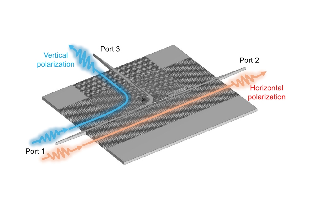
Small-scale PICs (SS-PICs): These circuits range from 2 to 10 functions or components integrated into a single monolithic substrate. Examples include lasers with integrated modulator and maybe some ancillary components like rear-facet PIN monitor, variable optical attenuators (VOA), or tuning element. Small-scale PICs typically only integrate a few functions for a single wavelength, or several channels of the same device (i.e., laser diode or PIN arrays).
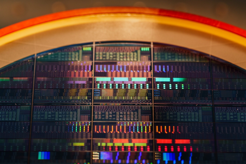
Medium-scale PICs: These circuits range from about 10 to 100 functions or components integrated into a single monolithic substrate. This can include the addition of several functions for a single wavelength channel and even some small level of parallelism (i.e., multiple functions duplicated across multiple channels). Large-scale PICs: These circuits will be above 100 functions or components integrated into a single monolithic substrate, which may imply the integration of several functions for a single wavelength channel as well as a high degree of parallelism (i.e., 10+ channels per PIC). A good example is shown in Figure 2, a 282 functional element prototype PM-DQPSK transmitter in InP.
Very large-scale PICs: These circuits will be above 1000 functions or components integrated into a single monolithic substrate. This could include the integration of functions as well as wavelengths, but nevertheless is probably the barrier to digital-based PICs, and thus might be referred to as the Holy Grail for PICs.
6.0 Materials platforms for photonic integration
A wide variety of materials platforms exist which offer the possibility of photonic integration, and these generally mirror the materials used in the construction of both active and passive optical components.
Individual component devices that make up an integrated photonic circuit are generally best made from materials of different bandgaps and junction placements. For example, laser material must enable efficient light emission under forward bias, modulator material should allow low and high attenuation in the “on” and “off” states under reverse bias, and passive waveguides require a material with minimal absorption. A multitude of successful material integration methods exist for photonic integration. Optical components are built using many materials including indium phosphide (InP), gallium arsenide (GaAs), lithium niobate (LiNbO3), silicon (Si), and silica-on-silicon. Photonic integration derives its value from the ability to unify as many disparate functions into a single material platform, and thereby deliver maximum impact on system cost and functionality.
Lithium niobate has, to date, allowed smallscale photonic integration of several components. Devices have been built that integrate multiple Mach-Zehnder modulators and associated waveguides and couplers on a single substrate, for example. Complex processing requirements and size limitations, however, may preclude it from being a material of choice for scaling to medium or large-scale integration. Furthermore, lithium niobate faces severe technical challenges to practically implement active optoelectronics functions like lasers and detectors, thus limiting its potential to integrate the entire range of desired photonic functions.
Silicon, or silicon-on-insulator (SOI), has shown promise as a materials platform for the large-scale integration of passive optical devices such as arrayed waveguide gratings (AWG), optical switches, and VOAs. In recent years, integration of active devices have been commercialized—such as lasers, amplifiers, modulators, and photodetectors— which offer potential for low cost PICs. In addition, silicon photonic integrated circuits can be built using standard CMOS processes and therefore hold the promise for enabling both optical and electronic integration.
Silica-on-silicon has been used as the material of choice for the fabrication of planar waveguide circuits (PLC) which enable the integration of a large number of passive optical functions. PLCs that integrate more than 100 passive optical functions on a single chip are currently in routine production. Examples are chips integrating optical couplers, switches, VOAs, and monitor taps for use in ROADMs applications, and chips integrating multiple AWGs for use in wavelength selective switch (WSS) applications. Excellent examples of passive PIC products are shown in Figure 3.
Silicon is an indirect band gap material, which means that implementing active opto-electronics functions such as lasing and light detection will be more complex. Innovative approaches have included the use of novel material doping, different polycrystalline structures, and/or the need for external optical pumps. In the meantime, the relative maturity and ease of manufacture of this technology for use in implementing passive optical functions has led to the increasing use of silicon-based planar lightwave circuits (PLC) for integrating “alloptical” functions such as ROADMs.
Photonic integrated circuits can also be implemented using III-V materials having a direct band gap such as InP or GaAs. These materials inherently support light emission and detection, and can be used to integrate lasing, amplification, and detection functions that are important to implementing optical-to-electrical-to-optical (OEO) conversions. For example, GaAs allows the fabrication and integration of active optoelectronics devices in the 850 nm telecom window. Clear benefits are the short-reach optical transmission applications including chip-to-chip, computer-tocomputer interconnections, and local area networks.
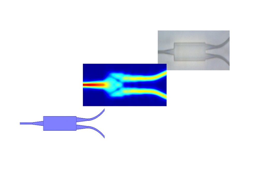
Indium phosphide and its many ternary, quaternary and penternary alloys have demonstrated the ability to marry the reliable integration of both active and passive optical devices operating in the 1310 nm or 1550 nm telecom windows. InP supports light generation, amplification, modulation, detection, variable attenuation, and switching in addition to passive functions such as wavelength (de-)multiplexing, optical routing, and polarization control. This enables all the main optoelectronics functions required in an optical transport system to be monolithically integrated into an optical “system-on-a-chip” that can provide substantial benefits versus the use of many discrete optical devices. A strong and growing player for PICs over the past few years is monolithic-hybrid integration. Here, III-V material is wafer bonded (adhesive or molecular) to a prepared substrate, most commonly SOI, and then further processed using modified or standard CMOS process technologies. In this case, the small critical dimension and high optical confinement of SOI may be combined with the light emitting and detecting properties of III-Vs. An example is shown from European researchers in Figure 4.
7.0 Has the reliability of PICs advanced for digitization?
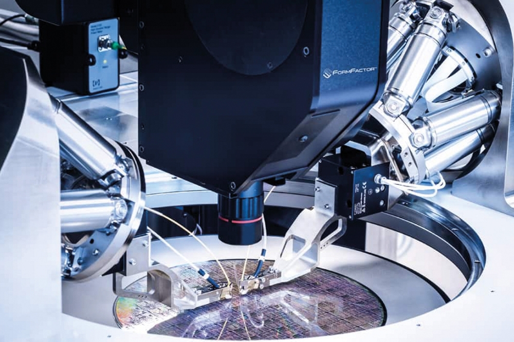
As with any new technology, reliability needs to be proved beyond a shadow of a doubt in order to carry traffic. The progress with InP PICs has been terrific to date, and is probably ready for digitization if and when the process technology advances to the level of maturity needed. Indium phosphide is now proving to be an excellent platform for integration as can be seen in Figure 5.
Currently deployed InP PICs implemented by Infinera to support 100 Gbps WDM per chip have demonstrated more than 100 million service hours with no failures. This puts the FIT rate for a > 50 functional component, PIC, at < 10 FIT for a 60% confidence level. This compares well to field data from discrete commercial 980 nm Pump Chips: 74 FIT @ 60% CL (H. Pfeiffer et al, OFC 2002) or 5 FIT (G. Yang, et al, JDSU, JWA30, OFC 2007). Improved reliability in PICs is being seen as one of the strongest drivers to grow photonic integration toward the Holy Grail of digitization.
8.0 The Holy Grail for photonics integration is coming
To better access the potential of reaching the Holy Grail for photonic integration, roadmaps need to be generated…derived by the industry and academia. There are presently only a few trend graphs for photonic integration, and perhaps this is a call to further explore the area between analog device integration and digitized integration for photonics. Two important trend graphs are discussed below that address photonic integration both from a component as well as a functional standpoint (using wavelength). Although the component devices have changed in nature and structure over time for PICs in fiber-based communications, the capacity that a single die can deliver doubled every 2.2 years during the 90s with time division multiplexed (TDM) communication networks. This is seen in Figure 6: the two round dots, lower left, for EML devices. Wavelength division multiplexed (WDM) integration on a single die allows for even more rapid growth using the pure III-V material system.
Figure 6 also shows the logarithm of data capacity in Gbps in the first year of deployment for commercial devices with solid diamond data points. Research devices and their predicted rate of development are shown with open diamond data points.
The trend for future performance is a log scale extrapolation from the reported highest capacity III-V prototypes reported in 2004 and 2008. There are a number of ways trend graphs can be shown, and in Figure 7, the trend towards large scale progressing quickly. The graph shows that by 2010, technology leaders should be in a position to address very large scale photonics integration, and perhaps digitization.
9.0 Metrics for PIC trend maps and roadmaps
The obvious way to address future trends is component count, with small, medium, large and very large scale integration metrics. An area in which photonics works well is functional count and functional integration. In functional count, active and passive functions are counted separately. Short definitions of active and passive functional components are provided below:
“Active” components: These are optoelectronics functions that require an electrical contact, such as lasers, PIN detectors, modulators, switches, VOAs, and amplifiers. A current (forward potential) may be injected into an active device to generate light by conversion from electrical to optical at a pn junction. A current may also be applied to change the local index of a component. A voltage (reverse potential) may be applied through an electrical contact to enable energy conversion from optical to electrical at a pn junction. A voltage can be used to change the local index of a component or to change the optical absorption properties of the material. A current may be applied through a resistive medium to change the local temperature of a device, which may or may not be the same material as the optical path material system. Most active elements have separate contacts for sourcing and sinking current. It should be clear that it is the function count, not the contact count that is tracked.
“Passive” components: These components enable purely passive functions such as waveguides, filters, power dividers, and multiplexers. Passive devices may indeed have electrical contacts in some cases for tweaking or tuning of the device performance. These electrical tuning functions are slow acting relative to the data rate of information being transported through them (often thermal in nature) and can be “set and forget” for the life of the device. These tuning functions are separate active elements from the passive device function.
It is possible to measure the technical level of advancement of the integration platform by aggregating the total number of active and passive functions on a yielded optical die regardless of the die’s application as a system or subsystem in an optical network. The philosophical intent is to track the beneficial effect of reduced defect density. Counting each device that can have a different failure mode is an easily applied technique which is independent of the method of counting random and systematic “killer” defects.
One issue with this approach is that each passive device is defined as one function regardless of the number of inputs and outputs. For example, an AWG which has 8 input and 8 output arms counts as one function, as does a similar AWG with 1000 input and output arms. The larger AWG may then have a greater chance of sustaining a killer defect than the smaller AWG. It may seem incorrect to count each device as one; however, as practical circuits get more complex, they will need larger and larger passive routing, multiplexing, and other functions. The same yield management improvements that enable higher active counts support larger passive elements, as well. In general, the size of shared passive elements will scale with the active element count. A single 1000 x 1000 port AWG die may not be as significant an achievement as one in which numerous active functions are multiplexed through that AWG on the same die. It is hoped that if this method is followed, all yielded die will be treated with similar rules.
Table 2 identifies key required areas of continued research and development in photonic integration and might be considered the beginning of a roadmap toward digitization.
10.0 Summary
If photonic integration had come first, the metrics would be different…but it didn’t. The photonic integration community needs to redefine integration metrics for the industry. Road and trend maps are good vehicles to accomplish this. Unfortunately, the route to full digitization in photonic integration will be slow given the traditional metrics from the semiconductor IC industry. With the progress of analog photonic devices and demonstrated levels of component and functional integration in the order of 100s, full digitization in photonics is still probably 5-10 years away. To accelerate the progress, there must be industry-wide efforts in the following areas:
-address common fabrication and process techniques
- better simulation tools to standardize device structures
- agreement in the industry for common devices with less custom specifications
- agreement in the photonic industry to utilize foundries
- common road and trend maps for both academia and industry
While a volume application is needed to bring competitive cost structures to photonic integration circuits, progress toward digitization will occur when economics are part of the design process: the design for low cost functionality. The massive application will certainly drive a cost-efficient solution; standardization will allow the production to be decoupled from the design as in foundry manufacturing.
It is hoped that large photonic foundries which operate on standard materials, processes, and design rules will permit mass production of highly complicated but more efficient PICs with building block architecture to feed those massive applications.
Digitization is the vehicle to unify the photonic integration industry. It may allow new metrics such as flops/sec, a common metric seen today in silicon digital processors, to appear in photonic-based systems. Only then will the Holy Grail of photonic integration be possible. Photonic integration has yet to achieve this digitized level of integration, and is currently in the analog domain from a functional as well as component standpoint.