Technical Insight
Intermixing drives photonic integration (Fiber-Optic Components)
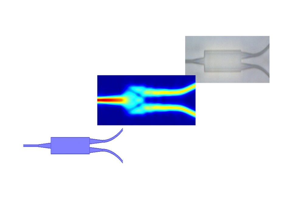
Quantum well intermixing could become a key process in developing next-generation monolithically integrated optical components, writes John Marsh of Intense Photonics.
In the field of optical communications, the transition from point-to-point systems to networks is demanding components with much higher performance. The improvements needed span a wide range of parameters, from more dynamic and flexible operation to better mechanical and thermal stability. The technology platform required to realize these advances successfully and cost-effectively needs to be extremely versatile. It must be capable of replacing a wide range of passive components with active elements, and of easy integration of both active and passive functions. Integration of discrete devices brings numerous benefits to the optical communications system designer. Losses associated with coupling to fibers are eliminated, and the number of packaging stages is redu-ced. Also, mechanical and thermal stability are greatly enhanced these are attributes which are particularly beneficial to functions required for the all-optical network, such as wavelength conversion and switching. Integration of different optical elements within a single device also supports advances in terms of functionality; this enables, for example, the realization of novel semiconductor lasers with high output power or ultra-short pulses. In developing monolithic photonic integrated circuits (PICs) for future generations of optical communications networks, Intense Photonics has chosen quantum well intermixing (QWI) as its fabrication platform, following many years of development and experimentation with different optoelectronic materials and device structures. This article introduces the technology, contrasting it with traditional bulk material and quantum well approaches to monolithic integration. Monolithic integration technologies Monolithic photonic integrated circuits are fabricated in either GaAs- or InP-based heterostructure material systems, depending on the application wavelength. Traditional approaches to monolithic integration, using bulk materials, make use of etch and regrowth fabrication techniques. The main steps to integrate a fundamental optoelectronic building block a gain region with a passive waveguide are illustrated in . An epitaxial structure, usually that of the gain region, is first grown across an entire GaAs or InP substrate. The gain region of the final device is masked using photolithography, and the device is then etched to create a slot for the passive waveguide. In a second stage of epitaxy, the passive waveguide is then grown into the slot. This process typically has low yield, due to the difficulty both of regrowing on a vertically etched surface, and of regrowing with high precision. A further problem is that the material selection necessitates a compromise between the bandgap, refractive index and layer thickness of the passive waveguide. There is inevitably a mode mismatch at the butt joint, resulting in losses due to scattering and back-reflection. There are significant advantages in moving to quantum well (QW) active layers. A QW is a very thin semiconductor layer, typically 10 nm, sandwiched between "barriers" of larger bandgap material. Because of the bandgap difference, electrons and holes are trapped in the QW. The small size of the well causes the electron and hole energy levels to become quantized, and so the bandgap energy of a QW is larger than that of an equivalent bulk layer. Although a QW confines carriers (electrons and holes) efficiently, because it is thin it does not confine light effectively, the wavelength of light being much larger than the well thickness. QW waveguide devices are therefore grown with separate waveguide layers, which comprise the waveguide core. Because the carriers are confined in the QW and the light is confined in the waveguide core, this type of structure is called a separate confinement heterostructure (SCH). An SCH is illustrated in . The optical overlap between the waveguide mode and a QW is much smaller than that between the waveguide mode and the waveguide core. This makes it possible to remove the QWs from the waveguide core, leaving a passive waveguide with identical dimensions and virtually the same refractive index. Scattering and reflection losses at the butt joint are, in principle, extremely small. However, if regrowth is used, the precision to which the layers can be grown in terms of thickness and composition determines the quality of the butt joint (). A different solution is to vary the width of the QWs across the wafer during a single stage of epitaxy. In this approach, which is achieved using selective area epitaxy, the substrate is coated with a dielectric mask in which slots are opened using photolithography and etching. No growth takes place on top of the mask, but surface migration of the growth species can take place for some distance across the mask to the nearest opening. The growth rate and hence the QW width in the opened areas therefore depends on the width of the opening and the patterning of the mask. The technique is quite limited with regard to the bandgap changes that can be achieved, and it cannot be used to pattern the bandgap across a wafer in two dimensions. A further integration approach, which is being used by Intense Photonics, is based on QWI. QWI is a technique that allows the properties of a semiconductor QW structure to be modified, typically allowing its energy bandgap to be increased. Multiple optical communications functions can therefore be integrated monolithically on a chip. Quantum well intermixing A variety of QWI techniques have been developed, including impurity induced, impurity free (dielectric cap), implantation induced and laser induced. Impurity-free techniques are highly preferable, since the introduction of electrically active dopants into a semiconductor waveguide results in optical absorption. The impurity-free vacancy disordering (IFVD) technique makes use of dielectric caps on the surface of the semiconductor to create vacancies on the group III lattice site. The vacancies diffuse through the semiconductor and, as a result, individual atoms hop from one lattice site to another. As a result of this process the QW intermixes with the adjacent barrier material. The IFVD process is illustrated in , which shows the atomic structure of an as-grown GaAs/AlAs QW structure, with a GaAs cap and a GaAs QW (a). The sample is coated with a layer of SiO2 and then annealed. At elevated temperatures Ga is soluble and has a high diffusion coefficient in SiO2, so during the annealing stage some Ga atoms dissolve in the SiO2 cap. Vacancies are created as a result of Ga atoms leaving the semiconductor, and these vacancies have a high diffusion coefficient in the semiconductor. The vacancies diffuse from their high concentration region at the surface to low concentration regions (the remainder of the semiconductor), with individual vacancies following a "random walk". The effect of the random walks of a large number of vacancies is to intermix the regular layered structure of the as-grown structure (b). The effect of intermixing on the band structure of the quantum well is illustrated in . The red lines show the conduction and valence bands of the as-grown structure. Because the central GaAs layer is a QW, the electron and hole levels are quantized, so the effective bandgap is wider than that of bulk GaAs. Intermixing causes Al to diffuse into the well, and Ga to diffuse out. This widens the well and increases its average bandgap (shown in blue). The bandgap of the intermixed QW is wider than that of the original well, allowing the intermixed structure to be used as a passive waveguide. An active/passive waveguide butt joint fabricated using QWI is illustrated in . It can be seen that a key advantage of the QWI process is that the active waveguide is in perfect alignment with its passive counterpart. Furthermore, the refractive index step at the butt joint can be designed to be negligible. The average composition of the waveguide core is identical in the active and passive regions. However, the bandgap of the QW has been changed by QWI, so the refractive index of the QW region is also modified, and this change in index can be significant as high as 5%. It has already been noted that the optical overlap between the waveguide mode and a QW is small, typically around 1%, so the change in index of the guided mode is around 103, a value that would be very difficult to achieve routinely using regrowth. The corresponding reflection coefficient at the butt joint is around 105. Applications of QWI Because QWI is highly suited for the realization of active/passive butt joints, it could become a key process in the manufacture of monolithic devices and PICs. Examples of component sections that have already been demonstrated using QWI technology include: Active Bandgap-tuned laser active regions, semiconductor optical amplifier gain blocks, semiconductor optical amplifier non-linear blocks, bandgap-tuned electro-absorption modulators, bandgap-tuned phase modulators, tunable gratings, saturable absorbers. Passive Low-loss waveguide interconnects, splitters and couplers, array waveguide multiplexers and demultiplexers, grating components, non-absorbing mirrors. QWI-based integrated components have already been fabricated by Intense Photonics. A simple example of the use of QWI is to make the mirror facets of a 980 nm laser non-absorbing to improve performance and yield. More sophisticated multi-function components combining a passive waveguide, gain section and saturable absorber have also been fabricated. The latter device implements a mode-locked laser producing picosecond pulses at a repetition frequency determined by the cavity length, and might be used as a source in an optical time division multiplexed system, or for all-optical clock recovery. The number of ways in which the sections can be combined is essentially unlimited, allowing completely new functions to be realized, including those required by all-optical network and future ultra-high-speed networks. Integration technology Intense Photonics has developed proprietary technology that allows QWI to be used to fabricate complex photonic integrated circuits in a production environment. This technology base includes: Thermally matched dielectric caps For IFVD to be an effective integration technology, separate dielectric caps are required to enhance and suppress intermixing. However, IFVD takes place during a high temperature anneal, and there will be large thermal stresses if the dielectric caps have different coefficients of expansion. These stresses can be sufficiently large to cause mechanical damage to the device. The process used by Intense Photonics effectively eliminates this problem. Scalable process The QWI process uses standard semiconductor processing equipment to deposit the dielectric caps. The process can be scaled in terms of both throughput and wafer diameter. Impurity-free process The IFVD process is impurity free, so no electrical dopants are introduced into the passive waveguide. Introducing electrical dopants would result in free carriers (electrons or holes) that absorb light, which means that the passive waveguides would have high attenuation. The IFVD process circumvents this limitation, and makes it possible to include long lengths of passive waveguide in photonic integrated circuits. Wide range of materials The same basic process has been used in both GaAs- and InP-based material systems, allowing it to be used in devices and PICs operating at important wavelengths such as 980, 1310 and 1550 nm. Intermediate bandgaps Varying the process parameters allows intermediate bandgaps to be realized. A chip with as many as 20 different bandgaps has been demonstrated using a single annealing stage.