Boosting satellite networks with flexible microwave photonics
In a project with ESA, LioniX International has developed a reconfigurable microwave photonics module that could transform satellite communications. This innovation illustrates how far PIC technologies have come and how effectively they can now be adapted to serve a diverse range of industries.
By Sadoon Al-Obaidi, Marketing & Communications Director, Charoula Mitsolidou, Systems Engineer, and Ioana Mateciuc, Marketing Assistant, LioniX International
The ubiquity of generative AI in today’s world, both as a content-making tool and as a successful business case for PICs, has quickly become well-trodden ground. Of course, for industry insiders this is nothing new. Pluggable transceivers were already the biggest market for PICs before 2022, when popular software like DALL-E 2, Stable Diffusion, and ChatGPT were released for public use. For the PIC specialists, they are not where the intrigue lies. Instead, what everyone wants to know is: what will be next? Of all the possible applications of PIC technology, bursting with potential as it is, what device will combine the performance boost, market necessity, and ease of production to make the big time?
Will quantum computers finally take the crown from GPU computation? Is PIC-powered LiDAR on the verge of appearing in every car? How many disposable PIC sensors will personalised medicine need for rapid drug testing? Each of these applications requires entire ecosystems, with variations on product developers, design houses, chip foundries, assemblers, test labs, you name it. The technology is flourishing; if only we could know which of the many innovations will take off.
To be clear, we will not be consulting any oracles here. Aside from the Euro 2024 office pool, LioniX International is not in the betting business. But our module development work does make us regular optimists. We have seen design and processing principles, developed through more than 20 years of operation, prove capable of realising a range of disparate applications. We have converged on some basic rules to follow, like using each photonic integration platform for what it’s good at, designing the whole device before designing the photonic circuit, and involving the application experts as much as possible.
Figure 1. A general schema for satellite communication signal processing.
The PIC ecosystem has been arriving at the same conclusions, too. We now see a thriving PIC field, with many new and established firms following the same principles to tackle a wide range of problems from different angles. So, we are in no rush to have a horse in the race. Instead, our vertically integrated structure allows us to see the potential of PICs actualised for different markets, in novel modular devices, time and time again. Which brings us to the subject of this article: a particularly exciting recent in-house development in the form of a fully adjustable satellite communications (satcom) channel selector, functional across three microwave bands (Ka, Q, and V), from 300 MHz to 300 GHz.
Microwave communications is its own highly sophisticated field, rivalling even quantum processing in complexity and technical considerations. Diving into this world, we will explore how the function, design, and production of microwave communications come together, and how this technology can revolutionise satellite communications. But this is just one compelling example of a broader take-home message: PICs have reached a level of maturity that lets us build high-performance, energy-efficient devices for virtually every industry.
The question isn’t whether PICs can prove themselves again with a second killer app; the question is which market will be next to find its great leap forward with PICs.
Figure 2. Schematic representation of the 4-channel (DE)MUX filter
module. The 4 independent paths leading out of the tuneable splitter
each connect to an independent set of CROW and lattice filters. The
power distribution is selected by the splitter, the CROW filters carve
off the user-selected channel, and the lattice filters clean up the
spectrum.
Crowded bandwidth, crowded orbit
The satcom industry faces an old monster in an evolved form. As telecom providers plan for bigger data rates through 6G networks and beyond, satcom must accommodate that need within a limited available bandwidth. There are a few options, but the industry has yet to converge on a solution for allocating the limited bandwidth where it is needed.
The status quo of satcom is that each conventional satellite is sent to orbit with a payload of electronics that processes signals in one specific way (Figure 1). They receive a low-power broadband signal from a ground station, which the satellite splits into different channels (demultiplexing, DEMUX). These component signals are frequency-shifted, filtered clean, then power-amplified separately, recombined into a single signal (multiplexing, MUX), and sent back to Earth.
This process of DEMUX, filtering, amplification, and MUX, is pre-programmed before the satellite is launched. The signal processing system is set, with no possibility of reconfiguring any of it once it is in orbit. If there is a signal that needs to be processed differently in some way, this can only happen if a different satellite equipped for the task is already launched into orbit.
One solution would be to populate space with as many satellites as necessary to handle the different processing routes. But there are many reasons why this would be far from ideal. Besides the high financial and material costs of launching so many satellites, this approach would clearly contribute to the serious problem of space debris, potentially triggering an ablation cascade – in which one collision results in more debris that makes further collisions more likely. Moreover, large numbers of satellites also interfere with astronomical research by simply blocking the view. The phrase “single-use satellite” may sound absurd, but the problem is inescapably reminiscent of plastic production and consumption.
The alternative is flexible satellites that can be reconfigured in orbit, ‘at runtime,’ to process different kinds of signals as needed. Far from trivial, this goal is a focus of much R&D effort in the space sector. The electronics of flexible payloads are difficult to realise, while the equipment required to do the necessary signal splitting, filtering, amplifying, and combining is bulky, heavy, and energy intensive.
For a reconfigurable electronic payload, the required components start to pile up, making the whole endeavour less efficient. But our emphasis on ‘electronic’ here is not incidental. ICs may be the original kind of integrated circuit, but PICs have exactly the right set of advantages to tackle this problem.
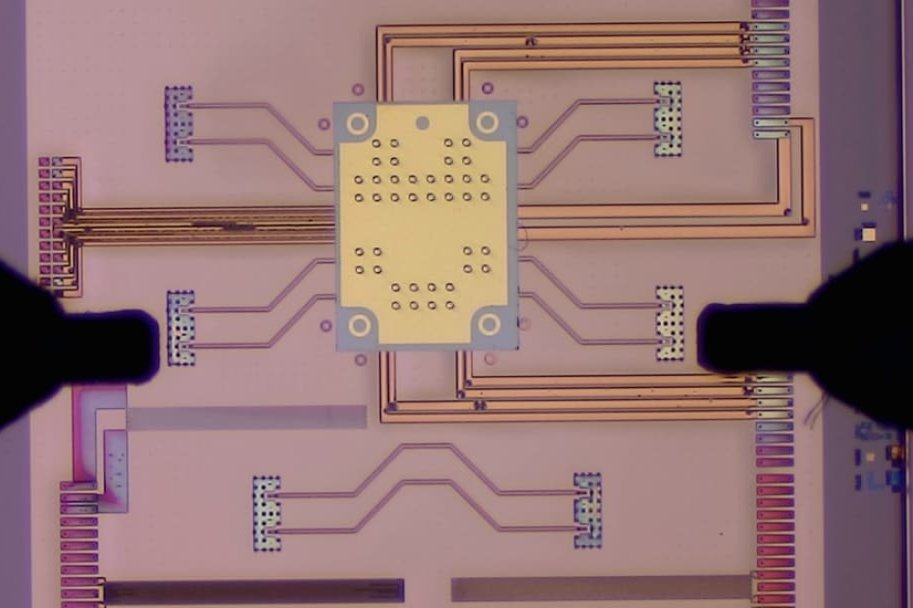
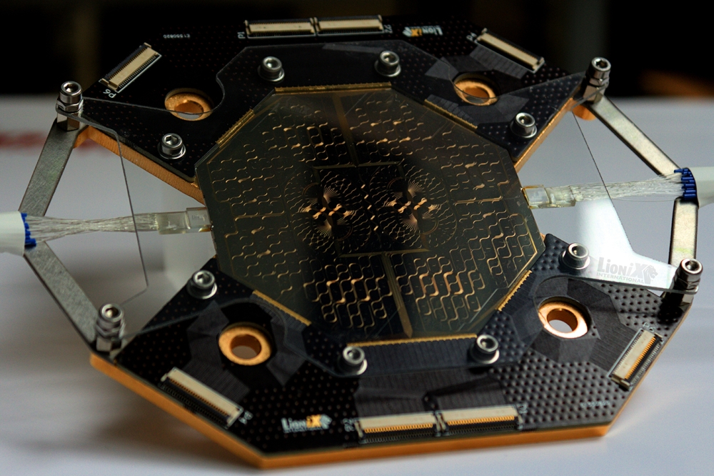
Figure 3. A closeup of the ThoRmux module, with the 1:4 splitter and
CROW filters in the chip centre, surrounded by an aMZI lattice.
Wirebonds connect the PZT actuators to the surrounding PCB, which route
to ribbon cable connectors.
The field of integrated microwave photonics (iMWP) in general addresses the need for photonic techniques to generate, distribute, process, and analyse high-frequency and broadband electronic signals, all on PICs. Compared with alternatives, PICs sidestep inherent obstacles like electromagnetic interference and crosstalk. They also bring their own distinct advantages, from performance enhancements and stability, to size, weight, power, and cost (SWaP-C) improvements. Furthermore, iMWP enables entirely novel functions in analogue components. For example, iMWP filters provide key advantages that surpass the performance of current state-of-the-art electronic filters. These include broadband tuneability and reconfigurability, as well as high frequencies, up to the terahertz range.
This is the context within which project ThoRmux aims to excel. In collaboration with the European Space Agency (ESA), Sener Aerospace, and Charles III University of Madrid, LioniX has been developing a tuneable iMWP radiofrequency (RF) DEMUX system, which allows flexible frequency allocation within broadband signals.
At the heart of the system is a PIC-powered (DE)MUX filter module, which enables multiplexing and demultiplexing of multiple channels with reconfigurable bandwidth and central frequency. The system makes use of our ultra-low-loss silicon nitride platform, TriPleX, and our holistic PIC module approach.
Figure 4. Simulated spectral response of the 4-channel DEMUX filter.
What’s in a channel selector?
An iMWP module works in the context of electronic RF systems. Hence, for this module as well as others, the chain of operations includes light generation for the carrier signal, modulation (to up-convert and encode the RF signal into the light), the application-specific operation of the device (in this case, filtering), and finally, detection (to convert the light back to RF).
The ThoRmux DEMUX module specifically covers filtering, and is designed to process a broadband signal carrying 4 RF channels. Its function can be summarised as a channel selector. As shown in Figure 2, it is schematised as a tuneable 1:4 optical splitter, a set of filters based on coupled ring-resonator optical waveguides (CROW) for an infinity impulse response (IIR), then a set of filters based on a lattice of asymmetric Mach-Zehnder interferometers (aMZI) for a finite impulse response (FIR).
The first set of filters, based on CROWs, is the primary bandpass filter of the channel selector. They select each channel’s central frequency and regulate its bandwidth. The filters have been designed for operation at 1550 nm and exhibit a free spectral range (FSR) of about 2.5 GHz. TriPleX silicon nitride has demonstrated optical losses lower than 1 dB per metre, which enabled the realisation of these microring resonator (MRR)-based filters with extremely high quality factor (Q factor up to 300.000). This results in high-resolution bandwidth and sharp roll-off filter response.
The second set of filters, based on aMZI lattices, serve as FSR extenders. CROW filters produce 2nd and 3rd parasitic passbands, which limit the FSR of their response. These lattice filters act as secondary band-stops, suppressing the parasitic passbands and extending the FSR of the channel selector to about 10 GHz. The distinct advantage of aMZI filters is that they can be realised with an unlimited FSR, whereas MRR filters are limited by practical considerations regarding their components, such as waveguide bending losses and phase shifter lengths.
As each of these components is independently addressable, the channel selector can be fully reconfigured; each channel’s central frequency and bandwidth can be tuned across the Ka, Q, and V RF frequency bands. What’s more, once it is tuned, it uses very little power. Our lead zirconate titanate (PZT) stress-optic actuators, used to tune the filters, have about 1 µW per actuator of power dissipation in quasi-static operation. Set it and forget it, until you want to reset it.
Figure 5. Simulated CROW filter power responses for different frequencies.
A flexible module needs lean work
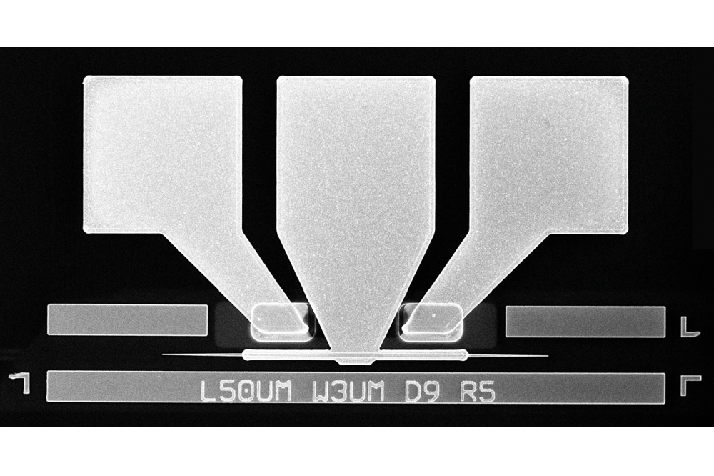
Now we can inspect the device with an eye for its function. The TriPleX PIC comprises the majority of its surface area, in the middle of which are the 1:4 splitter and the 4 “mandala”-shaped IIR CROW filters (Figure 3). Blossoming out from these are the aMZI-based FIR lattice filters, which fill the rest of the chip.
The optical inputs and outputs are interfaced to fibre arrays at the east and west, while the tuner electrodes are placed on the diagonals and wire-bonded to a custom PCB.
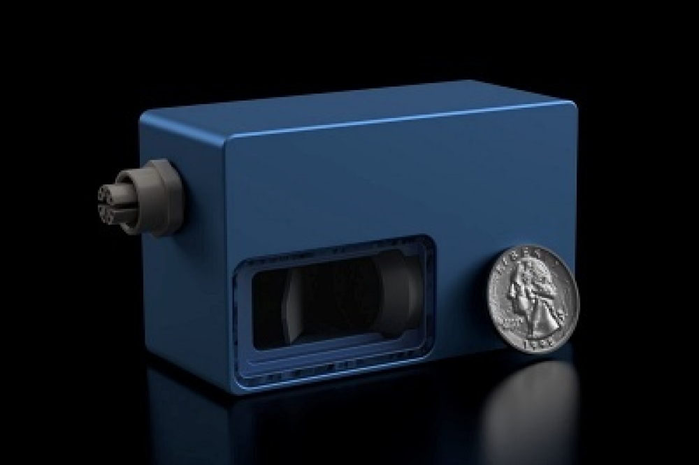
The assembly is mounted on a copper sub-mount, with flat cable connectors that provide connectivity to the control electronics. A total number of 318 PZT-based tuning elements are employed to tune and reconfigure the various photonic filters in the device. Since the quasi-static power consumption per actuator is ≈ 1 µW, the total power consumption in the PIC is lower than 320 μW for the entire module. The total assembly spans 129 mm × 135 mm × 5 mm.
It takes a village to raise a child, and it took the whole LioniX team to make this module. The nearly 4 metres of optical path length necessitated the use of ultra-low-loss TriPleX for the successful integration of the device. The circuit design had to consider the essential reconfigurability of the device and the long total waveguide length. It also had to take into account how the actuators could be connected to the control electronics, which meant that assembly and packaging considerations were included from the start.
From a chip fabrication point of view, everything from the splitting of the circuit design across multiple reticles and arrangement of processing tolerances, all the way down to polishing for optical integration, presented engineering challenges of their own. Finally, assembling this device, including the fibre array integration and wire-bonding, took practised expertise and operational flexibility.
The device is currently undergoing testing and characterisation in our labs. Early simulation studies showed very promising results vis-à-vis the filters’ spectral response; simulations predicted flexible bandwidth reconfigurability, with the tuneable bandwidth ranging from 125 MHz to 1 GHz (Figure 4). This is achieved by adjusting the power coupling coefficients of the tuneable couplers between the 8 MRRs of the CROW filter.
We also simulated central frequency tuning of each channel selector filter’s cascade. For the case shown in Figure 5, we turned the 4 individual passbands to have a channel spacing of 2 GHz. This is done by adjusting the tuneable phase shifts of the CROW MRRs and the lattice aMZIs. In general, the passband of each of the 4 channel selectors can be arbitrarily set to a different central frequency.
These simulation results have been presented in detail at the International Conference on Space Optics. The results of the ongoing characterisation work will be the subject of an upcoming talk at Photonics West. We don’t want to spoil too much, so here’s a buttoned-up teaser: the results are in good agreement with the simulation.


