Extremely high-power transmitters for access networks

Sources that combine a laser, a modulator and an amplifier in a single device are laying the foundations for high capacity access networks.
BY HÉLÈNE DEBRÉGEAS FROM ALMAE TECHNOLOGIES
Due to the phenomenal rise of YouTube and TikTok, many are watching more content on-line. To accommodate this trend, there’s been a tremendous rise in internet traffic, with this growth showing no sign of abating. Consequently, capacity has to increase throughout the fibre-optic network, from the long-haul links that span many thousand kilometres to the shorter connections, such as the optical access networks providing the ‘last mile’ between internet service providers and their customers.
Given this state of affairs, it’s not surprising that optical access networks are continuing to be rolled out at great pace. And as well as this additional deployment, throughput is on the up – initially, transmission speeds were 2.5 G, recently they climbed to 10 G, and sometimes data rates are now as high as 25 G and even 50 G.
Unfortunately, increasing the capacity of optical access networks is more complex than it appears at first glance. While sources with higher optical modulation rates are essential, they are not the only factor that matters.
In addition, there’s a need for a high optical power, because access networks – also known as passive optical networks (PONs) – have no optical amplification, setting them apart from other long-distance networks. This lack of amplification means that the losses resulting from propagation in the fibre and splitting among multiple end users ultimately limit both the network’s geographical coverage and the number of its end users.
To optimise the capacity of PON networks, they must include highly sensitive photodiodes that detect the low optical power they receive, and transmitters delivering the highest possible output power. For current applications, such as 10G-PON, 25G-PON and 50G-PON, the modulated power in the fibre needs to be around 4 mW. However, to increase capacity, new access networks are demanding a modulated power of up to 10 mW in the fibre, with even higher values sure to follow.

Figure 1. An illustration of a Passive Optical access Network (PON).
For upstream transmissions – that is, transmissions from the end user to the network – O-band wavelengths are used. This spectral domain, which is around 1.3 mm, benefits from an absence of chromatic dispersion in the fibre. A lack of distortion of the optical signal results, enabling implementation of powerful yet low-cost transmitters on the user’s premises. In this case, the most suitable source is the directly modulated laser: by simply modulating the electric current injected into the laser, modulation of the emitted power follows.
It’s a very different story for downstream transmission, which involves the transfer of data from the network to the end users. Wavelengths used for this task vary, ranging from 1342 nm for 50G-PON to 1577 nm for 10G-PON. However, in all cases, there is significant chromatic dispersion in the fibre.
One troublesome consequence of this dispersion is that the quality of the signal that’s emitted by directly modulated lasers is insufficient for transmission with an acceptable degree of errors. Due to this, externally modulated lasers (EMLs) are deployed for downstream transmission in access networks. This class of laser comprises two sections: a laser, powered by an electrical current, that emits a constant optical signal; and an electro-absorption modulator section, which is transparent at zero voltage, but absorbs light under a negative voltage. Through application of a modulated voltage, typically between 0 V and -2 V to the modulator section, successions of bits 0 and 1 can be transmitted at high data rates.
The downside of the EML is that it is more expensive to manufacture than the directly modulated laser. However, the additional cost is acceptable, because the component is only deployed in core network terminals and not on the user’s premises. The EML has a high reputation, thanks to its capability to transmit a much higher quality signal: there is a strong power contrast between the 0s and 1s; and there is high spectral purity, ensuring the source is resistant to chromatic dispersion. Following continuous improvements to EMLs for access networks, the modulated power in the fibre now reaches the order of 4 mW, meeting today’s needs.
However, while the power provided by the EML is adequate for access network coverage, it is still a limiting factor. What’s more, this weakness is only going to become more of an issue, as a further power increase is a key differentiator in next-generation high-capacity access networks.
A radical approach is needed to address this concern, because EMLs are getting close to the glass ceiling for their output power. Even if the power of the laser section is increased, it’s not possible to maintain the performance of the modulator. That’s because there is an intrinsic issue, associated with absorption of photons that create electrical carriers in the modulator. As the injected power increases to a very high value, carrier evacuation cannot keep up, so the carriers accumulate and screen the voltage that’s applied to the modulator. Making matters worse, the photogenerated electric current creates an opposing electric voltage in the modulator supply circuit. Both these effects contribute to a distortion of the signal emitted by the EML, and impose modulation voltages that are too high for implementation in the system.

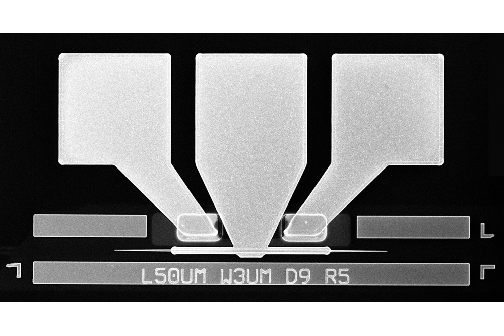
Figure 2. Top view image of a high-power transmitter (EML-SOA),
including laser – modulator – amplifier – output passive tilted
waveguides.
Amplifying concerns
Offering a way forward that allows the realisation of modulated powers of 10 mW or so is the addition of a third section to the EML: a semiconductor optical amplifier (SOA). With this refinement, injection of an electric current into the SOA ensures optical gain in this section through a multiplication of the photons that are passing through it. In theory, the SOA simply boosts the power emitted by the EML.
There are several advantages that come from this approach. First, the EML no longer needs to emit as much power, since there is now optical gain from the SOA that is located after the modulator section. Thanks to this refinement, the problems associated with modulator saturation and the loss of modulation efficiency are eliminated. What’s more, as the SOA section is very similar to the laser section, it can be manufactured using the same processing steps. The only noteworthy change is that the surface area of the chip increases. Finally, the SOA section improves the quality of the optical signal through the addition of so-called negative chirp, increasing the capability to combat chromatic dispersion in the fibre.
However, it is far from simple to enjoy all these benefits. That’s why the EML-SOA is only starting to be offered as a practical option for the transmitter. Note that great care is needed when taking this approach, because there is the threat that the SOA can severely degrade the performance of the EML.
One of the causes of this is that the SOA suffers from saturation. When too much optical power is injected, the density of photons propagating and multiplying reaches a value that leads to the consumption of all injected electrical carriers. At this point, the SOA fails to provide amplification, a condition described as gain saturation. This is highly problematic, as when the modulated optical signal injected into the SOA goes from a bit 0 to a bit 1, the injected power suddenly increases and the gain saturates in a few hundred nanoseconds. Due to this, the power of bit 1 gradually decreases, resulting in very high noise levels for bit 1s, an issue that prevents data transmission.
A second concern is that the EML is very sensitive to optical feedback at the output facet. While most modulated light leaves the chip, a small portion is reflected by the facet and excites the laser section, which begins oscillating at a resonance frequency of a few gigahertz. This oscillation totally disrupts the emitted signal, preventing the correct transmission of the information bits. To limit this effect on an EML, an anti-reflection coating of around 0.01 percent is applied to the output facet.
However, with the EML-SOA, optical feedback is amplified by around a factor of ten as light traverses back and forth along the SOA. Due to this, there’s the need for a 0.001 percent facet anti-reflection coating, which is not industrially feasible.
Finally, the SOA section requires an additional electrical current. However, this is restricted, because there’s a need to limit the power consumption of the transmission modules. It can be assumed that the total for the laser and the SOA should be in the same range as the current for just an EML laser.

Figure 3.(Left) Output power produced by the semiconductor optical
amplifier as a function of input power. (Right) 25 G eye diagram with
mask margin.
Addressing the challenges
At Almae Technologies of Marcoussis, France, we have tackled all these concerns while developing an EML-SOA for emerging high capacity access networks. Our device, suitable for 10G-PON and 50G-PON, targets a very high modulated power in the fibre of around 10 mW. To realise this level of performance we have adapted the design, so it is capable of a high-quality modulated signal and a low power consumption.
Our design excels by incorporating a fourth optical waveguiding output section, comprising a bend leading to a 7° output tilt, and a section without a waveguide where light diffracts. Thanks to this architecture, the optical mode is very wide and at an angle of 7° when it encounters the 0.01 percent anti-reflection coated output facet. This ensures that the small portion of reflected light is strongly spread out spatially, forming an angle of 14° with the optical guide. It is a configuration that ensures 99 percent of the reflected light is radiated, while just 1 percent is recoupled into the optical waveguide, where it could possibly disturb the laser section. The combination of the tilt and the unguided zone ensures that despite the SOA section, the device remains compatible with a standard 0.01 percent facet anti-reflection coating, while avoiding laser oscillation.
When designing our EML-SOA, we did not focus on optimising the laser section by placing our emphasis on a high power and low threshold current, but directed our attention to the SOA section. For this part of our device, we placed a premium on realising the highest possible SOA saturation output power. To achieve this, we selected a stack of semiconductor layers that reduced propagation losses, and ensured a less-confined optical mode to avoid too high a photon density. These choices enabled us to more than double the saturation output power of the SOA.
With these optimisations, our EML-SOA operates at record output powers, without any degradation in the quality of the modulated signal. For deployment in 50G-PON networks, our device provides 4 mW modulated in the fibre, for an EML with a laser current of 110 mA; and 10 mW modulated in the fibre, from an EML-SOA with only 135 mA of total laser and SOA current. And for the 10G-PON, we go from 3.5 mW modulated in the fibre with an EML having a laser current of 110 mA to 7 mW modulated in the fibre with an EML-SOA having a total laser and SOA current of just 150 mA. If it seems that there are too many numbers to digest, just note that we have more than doubled the modulated output power for an increase of only 20-30 percent power consumption.
Our EML-SOA results are extremely important for next-generation access networks because in addition to increasing the modulation rate, they open the door to very large capacities, in terms of both geographical coverage and the number of users. Our devices are currently in pre-production phase, with market launch slated for later this year.
It is possible that our technology may also have a role to play in other networks. It is unlikely to be deployed in long-haul networks, as in this case transmission is in the C-band, centred around 1.55 mm, where signals can be amplified by erbium-doped fibre amplifiers. But our EML-SOAs might serve in networks involving O-band transmissions around 1.3 mm, as today they do not have any form of in-line optical amplification. The O-band is used for interconnections between datacentres (400 G Ethernet and beyond), with data transmission supported by several very high-speed 100 G EMLs. Here the transmission distance is limited by the optical power budget to around 40 km, and the introduction of our high-power EML-SOAs could increase that distance by several tens of kilometres. So it’s clear that our device has plenty of promise.