Supercharging PICs with advanced design

Design tools that combine flexibility and precision can speed up design cycles and reduce the number of iterations needed, accelerating PIC technologies to market.
By Martin Fiers and Chiara Alessandri from Luceda Photonics
When a photonic circuit designer sends a drawing to a foundry, they are making a significant commitment. Depending on various factors, such as the volume and whether the wafer run is shared or dedicated, they will typically have to pay somewhere between €10,000 - €1 million and wait 4-9 months to get the manufactured circuit back. If they find there is an error in the prototype, then it will be an extremely expensive one; they will have to correct their design and go through another iteration, incurring the same cost in time and money again.
And beyond the expense to the company, there is a broader cost to the PIC industry and society as a whole. From photonic biosensors for diagnostics to LiDAR for autonomous vehicles, we know that PICs could be instrumental in achieving multiple exciting technologies, with the potential to transform healthcare, transport, computing and more. Anything we can do to reduce the time to market brings us closer to realising these benefits in people’s daily lives.
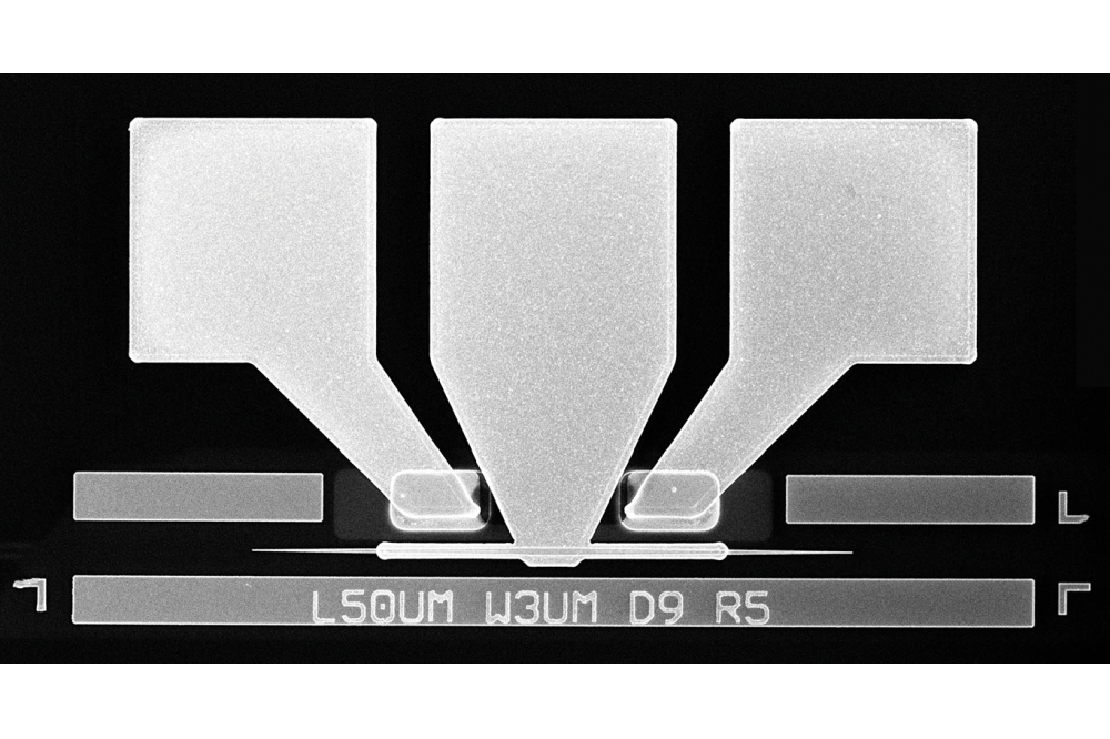
But these circuits are highly complicated devices, requiring extremely precise design and fabrication – even a seemingly tiny error in a circuit’s physical layout can have a decisive impact on how the chip functions. To illustrate this point, Figure 1 shows an example of two real designs for a PIC wavelength demultiplexer. The designer initially sent the one on the left to the foundry, but when he received the chip back, he discovered its performance was significantly poorer than he expected.

Figure 1. The two PICs might appear identical, but the one waveguide in
the one on the left is about 200 nm too long. This significantly impairs
its performance as a wavelength demultiplexer.
It turned out that one of the waveguides in the drawing is just fractionally – about 200 nm – too long, and this is enough to lead to an extra π phase shift that significantly impairs the circuit’s ability to separate the frequencies. The design on the right is correct and performs much better. Yet, to the human eye, they appear identical. This is just one example, but there are many different types of errors that are hard to spot, even after a careful design process.
So, rather than asking designers to pore even more painstakingly over the drawings, we could instead create tools that are specifically designed to make it much easier to generate the correct layouts, and which flag errors that have cropped up as automatically as possible. This is where the Luceda Photonics Design Platform comes in. With its flagship product IPKISS, the platform supports designers throughout the whole design flow, from the initial ideation phase, through component and circuit design, to functional validation and tape-out preparation.

Figure 2. IPKISS has a library of common PIC components. Users can also write code for custom components, which then become reusable IP blocks.
Flexible component design
We often draw comparisons between electronic circuits and photonic circuits, but, when it comes to design, there are some important differences. In electronics, designers can usually work with a set of standardised building blocks: transistors, resistors, and capacitors. In photonics, on the other hand, there is a much larger number of possible components – and more variations of each component – that designers can choose from.
IPKISS has a library of many of the most commonly used elements for designers to quickly add to their circuits, some of which are shown in Figure 2.
However, many PIC designers need to create custom components specifically tailored to their technology and use case. IPKISS therefore uses a flexible code-based approach, based on the Python programming language, which is more expressive than a graphical user interface. With IPKISS, designers create PIC devices and circuits by writing IPKISS code based on Python, from which the software can generate the layout. In addition, their custom building blocks become reusable IP blocks, that can be employed throughout the lifecycle of the product, or even be applied to different products and projects.
A major advantage of using Python in particular is that it has become widely adopted as the standard programming language in many science and engineering disciplines, and is being taught as part of many technical degrees. PIC designers are therefore likely to already have the coding knowledge needed, making it maximally accessible and convenient. It also comes with many libraries for visualisation, analysis, and integration.
Additionally, Python is a superb language to automate the design flow, offering the possibility of fine-tuning and adjusting the code to each organisation’s unique requirements, as well as giving the user control over the tiny details that can make or break a photonic device or circuit.

Figure 3. PICs made in different materials will also need to have a
different physical structure if they are to perform the same function.
The circuit on the left is in SiN with a bend radius of 80 µm. The
circuit on the right is in silicon with a bend radius of 5 µm.
Precise circuit design
While offering a high level of flexibility, the code-based approach makes no sacrifices in terms of precision. Designers have full control over all aspects of the layout; they can specify exact quantities for various parameters within the Python script, and can also add formulas for many key characteristics of the circuit.
Going back to the example of the error in the demultiplexer PIC, a designer could use IPKISS to avoid such a mistake by specifying in the code exactly how long each waveguide should be. The software can then create the correct waveguide layout and verify it afterwards.
If a designer wants a property, such as the Free Spectral Range (FSR), to have a specific value, they can add a formula to extract the correct layout parameters based on this property’s value. Executing the IPKISS code will then generate
an adjusted layout to yield the desired result.
This avoids the need for designers to redo calculations, thereby reducing errors, and enabling them to quickly and conveniently adjust key characteristics if they need to .
Another challenge that PIC designers face is that the correct drawing for a particular chip differs depending on the fabrication material and manufacturing methods of the specific foundry they are sending it to. For instance, the refractive index contrast is different for silicon (Si) than it is for silicon nitride SiN – two common PIC materials.
This means that, to manipulate light in the same way and get the same effect from chips made in these two materials, the physical size and structure of the circuits will in fact need to be different, as shown in Figure 3. To make it as quick and easy as possible for designers to navigate this, Luceda Photonics collaborates with multiple foundries to provide designers with the necessary design rules, geometries and building blocks associated with each one. Within the software, once a designer has the base code for their chip, they need only import the correct foundry and run the IPKISS script to generate the appropriate drawing.
An added benefit of this code-based approach to PIC design is that fabless companies have more flexibility about which foundry they work with, so they can compare the different technologies available and see which one fits their application best. Being able to easily switch between foundries also reduces supply chain risks, compared with relying on just one provider.

Figure 4. IPKISS Canvas generates schematics that makes some common
errors more visible. For example, the schematics here show whether there
is a break or abrupt change in a waveguide – something which is
difficult to spot by looking at the small segment of the layout on the
right.
Simulation and functional verification with IPKISS Canvas
While the features described so far can help designers from the start of the design process, these circuits are incredibly detailed, so the layouts need to undergo a thorough design validation process once they have been generated. IPKISS can help at this stage too, with a feature, graphical user interface (GUI) called IPKISS Canvas, which generates schematic diagrams from a designer’s Python script. These schematics are abstract representations that visualise the components in the circuit and how they are connected, making several types of errors much easier to catch.
For example, if there are any abrupt changes in the size of a waveguide in the circuit, or any breaks in its continuity, they might be almost invisible in the layout.
However, as shown in the Figure 4, the schematics make them more visible, so designers can spot and correct them without having to zoom in on every tiny part of the drawing. In this way, the schematics can help verify optical connectivity, ensuring smooth, tapered transitions and minimising loss. This feature can also help with checking electrical connectivity, showing where wires cross unintentionally and where they could short the electrical signal.
With IPKISS Canvas, users can annotate any crucial information from the layout on the schematic, such as path lengths of waveguides to compare path length differences. There are often specific requirements to match certain path lengths, and designers need exact control over the delays for light going through devices and circuits that are phase sensitive. These details are also included in the schematics, making it quicker to check whether the delays are what they should be.
Finally, in addition to circuit layouts and schematics, the IPKISS software can also run circuit simulations of how a PIC will function, putting virtual signals into the inputs and calculating the transmission it will produce, in both the frequency and time domain (see Figure 5). With this capability, designers can check that the output is what they are aiming for, flagging that they need to return to the PIC design to identify errors if it is not.
Future PIC design
Luceda’s long-term vision is to give photonics designers the same powers that electronics designers currently enjoy. We want to create a future in which PIC designers can depend on rapid design iterations, requiring only a minimal number of cycles to achieve the final, working device.
There are still challenges to overcome in making that vision a reality. Circuit models need to be standardised and calibrated for different devices, processes, and wavelength ranges, further improving the pre- and post-layout circuit simulations. As we continue to advance the IPKISS software, place and routing will further evolve to speed up the physical implementation, and additional verification at the functional level will give PIC designers more confidence that their intended design is properly captured and translated into the physical implementation.

Figure 5. IPKISS can run simulations of how a circuit will perform after
it has been physically implemented in the layout, indicating to
designers whether the layout might need correcting.
The latest version of IPKISS is a major step towards the goal of reducing the time to market. By offering designers both flexibility and precision in the design process, and by helping them catch errors with extensive verification features, IPKISS improves designers’ confidence that the circuit they have generated matches the idea they had in mind. In this way, the software reduces the risk involved in sending a circuit off to be manufactured. Ultimately, a faster time to market will be valuable for everyone who can benefit from the applications of this exciting technology.