Bringing photonic technology to 3D-stacked computing systems

Creating the low-latency “POPSTAR” optical network-on-chip through hetereogeneous integration on a photonic interposer.
By Stéphane Malhouitre, Leopold Virot, André Myko, and Jean Charbonnier from Université Grenoble Alpes and CEA-Leti, and Yvain Thonnart from Université Grenoble Alpes and CEA-List
Over the past few decades, optical devices have proven useful for high-throughput communication at multiple scales, from the Internet backbone to metre-range communication between compute nodes in datacentres and supercomputers. With ever-increasing baud rates, optical transceivers have demonstrated power efficiency at shorter scales down to board-level communication. Conversely, computing architectures stopped the gigahertz race more than 10 years ago in favour of greater emphasis on parallel execution. This shift requires increased communication between computing cores and memories, meaning that processor architectures have grown and core count has increased – in some cases up to the point where chip-level communication costs prohibit scaling.
Now, heterogeneity has become the buzzword for efficient computing architectures. Heterogeneous cores can be used for heterogeneous applications: following a trend from embedded systems-on-chip, it has become more efficient to have dedicated accelerators with specialised processing capabilities to perform distinct tasks, driving a shift from CPUs (central processing unit) to GPUs (graphical), NPUs (neural), and TPUs (tensor). Since packing all those accelerators and memories onto a single die rapidly becomes unfeasible, heterogeneous packaging solutions are needed to integrate multiple silicon dies implementing accelerators in modules stacked on an interposer. This approach benefits from 3D assembly technology involving multiple chiplets. It also allows the most appropriate technology node to be used for each chiplet to match the required performance, thus providing the highest energy efficiency.

Figure 1. (a) Optical network on silicon photonic interposer and (b) single-writer multiple-reader silicon photonic link.
The potential of interposer-based optical communication
To meet system performance requirements, communication between heterogeneous dies must sustain high-throughput at a low latency, while remaining within a low power budget. From this perspective, given its capacities at larger scales, optical communication is a promising option for ultra-short-reach die-to-die links. However, system optimisation goes beyond high-speed transceivers and point-to-point links. Thus, latency and power in computing systems are not only linked to distance, but also to routing and queuing costs.
Consequently, if only nearest-neighbour communication is implemented, heterogeneous architectures will encounter huge queuing latencies at every die interface for longer communication paths. To overcome this, we suggest the use of stacked systems on a large photonic interposer. This interposer serves as a base die for all the heterogeneous chiplets and allows implementation of an overall optical communication architecture between chiplets. Indeed, optical routing on the interposer removes the need for additional queuing and electro-optical conversion at each crossing in the network.

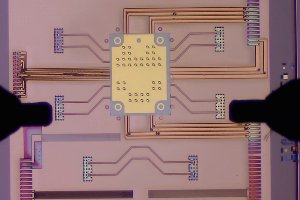
Figure 2. POPSTAR optical network-on-chip (ONoC) architecture.
The POPSTAR computing architecture on a photonic interposer
This architectural vision of an optical network on an interposer presents several challenges, from system requirements to implementation constraints:
• First, this interposer-borne optical network must be scalable according to the system requirements, with an appropriate interface between the chiplets and the network.
• Routing in the system should be decentralised to avoid the need for long-distance communication to a central scheduler for every data transfer.
• Unlike longer-distance transceivers, the associated interface must have a low footprint to create as little overhead as possible in the chiplets.
• Scalability and network topology must be considered in view of the optical power budget from the laser sources to the final opto-electrical conversion.
• As computing systems may have very unbalanced and variable activity ratios, power dissipation is not homogeneous, and temperatures can fluctuate by several tens of degrees during operation. These effects must not degrade communication within the optical network.
• Finally, the co-integration of multiple devices and process options must be possible without degrading individual device performances.
To address these challenges, we propose the POPSTAR optical network-on-chip (ONoC) architecture [1], with its ring topology of nested spiral single-writer multiple-reader (SWMR) optical links, as shown in Figure 1a. POPSTAR’s ring-based topology allows easy scalability. The optical interface of each die is fully standard and includes decentralised destination-based routing without intermediate routers. This interface leverages low-footprint microring resonators as modulators, and filters on wavelength-division multiplexed (WDM) links.

Figure 3. Schematic cross-section of POPSTAR ONoC with associated SEM images of fabricated devices.
The design includes a base SWMR link structure for each wavelength (Figure 1b), with a high-speed PN depletion-mode modulator on the transmission (Tx) side, and multiple low-loss PIN injection-mode filters on each potential receiver (Rx). Tuning these microring resonators involves thermal switching depending on the laser wavelength, which is enabled by closed-loop feedback and a dedicated remapping algorithm. This process makes it possible to lock close to the appropriate wavelengths while minimising the energy cost of tuning.
To route the optical data to its designated opto-electrical interface, during communication, only the Tx and relevant Rx adjust locking with voltage tuning of their filters to the laser wavelengths.
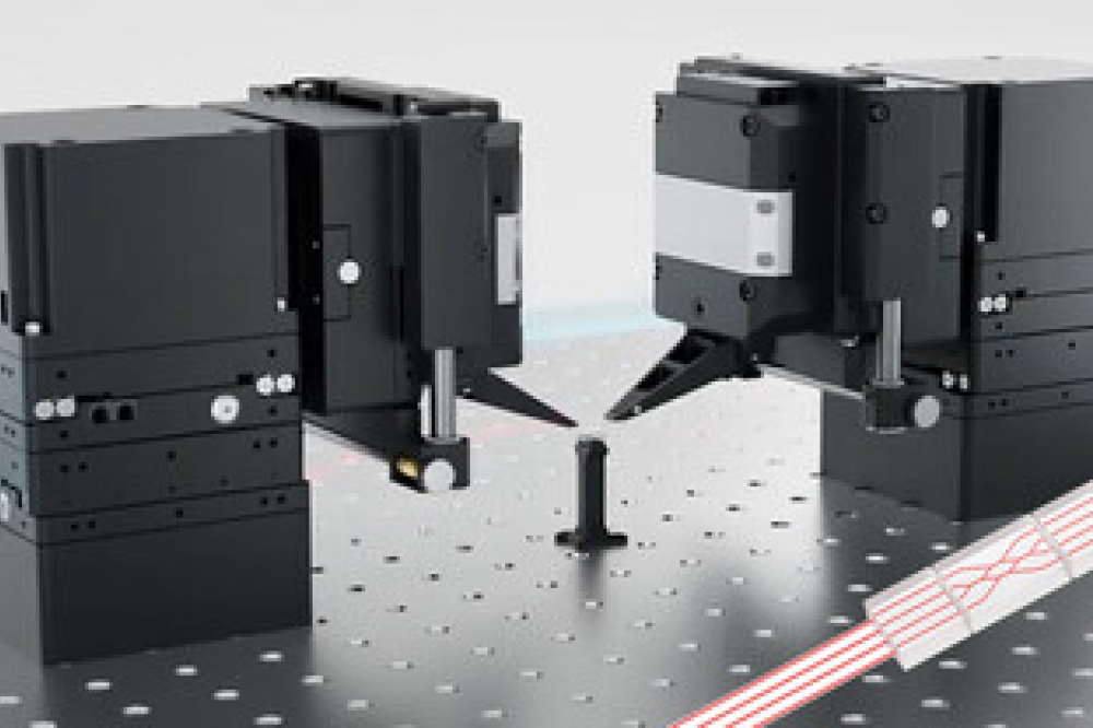
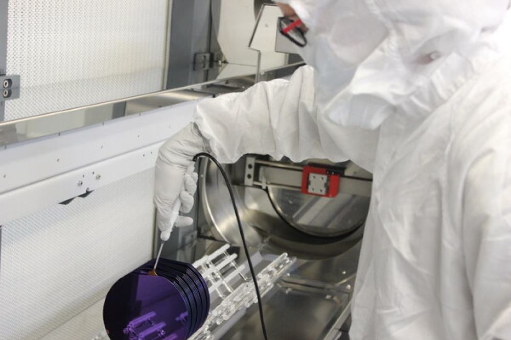
We have been working on creating a prototype of this architecture, connecting multiple 16-core computing chiplets with an optical network on an interposer. Each computing chiplet is associated with an electro-optical interface chiplet responsible for queuing, routing, and driving the optical network. Two additional electro-optical interfaces serve as primary inputs and outputs for the system, as shown in Figure 2. The computing chiplets were designed in a STMicroelectronics 28 nm fully depleted silicon on insulator support, whereas the photonic interposer is made using a dedicated process developed on an 8 inch silicon platform at CEA-Leti, combining silicon photonics and 3D integration.
Photonic and 3D process integration
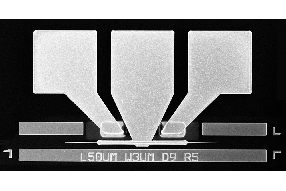
The photonic IC for POPSTAR ONoC shown in Figure 3 is composed of RIB silicon waveguides (Figure 3a) and specific features like single polarisation grating couplers (SPGC) and splitters [2]. Propagation losses in RIB waveguides are measured at 0.3 dB/cm, and SPGC shows insertion losses at about 3.3 dB, in accordance with the standard specifications for silicon photonic circuits.
The ONoC architecture is based on matrices of microring resonators (MRR) (Figure 3b) with PN-junction microring modulators for data encoding, and PIN-junction microring filters for data switching and routing. MRRs are fabricated with three patterning levels – resulting in three silicon thicknesses (300 nm, 165 nm and 65 nm) – combined with six implantation levels.
Lateral Si-Ge-Si heterojunction photodiodes monitor the readout of the optical signal (Figure 3c) with an intrinsic germanium area measuring 1 µm wide and 15 µm long. The germanium is epitaxially grown in a Si cavity. Photodiode responsivity exceeds 0.8 A/W at 1 V voltage bias, which is in line with the standard specifications for Ge photodiodes.
All silicon photonic devices are embedded in planarized silicon oxide. A standard CMOS process produces a silicide layer at the surface of contact areas on both the MRRs and photodiodes. This reduces the electrical contact resistance with back end of line (BEOL) levels. To optimise an MRR’s efficiency, it is accurately tuned using a patterned Ti-TiN thermal heater embedded in silicon oxide and placed on top of the MRR. The different components – MRRs, Si-Ge-Si PDs, and thermal heaters – are electrically connected by W contacts. A SiN passivation layer caps the W contacts before through-silicon via (TSV) (Figure 3d) processing.
TSVs manage the frontside to backside interconnections. The POPSTAR interposer integrates 12 µm diameter and 100 µm thick TSV middle process successively formed by reactive ion etching (RIE) of the top dielectric photonic stack (SiN/SiO2) and deep (DRIE) etching of the bulk silicon wafer.
A deposition of a dual silicon oxide layer (sub atmospheric chemical vapour deposition (SACVD) and plasma enhanced CVD (PECVD)) isolates the TSVs from the silicon bulk, followed by a Ti-TiN diffusion barrier deposition. Finally, a process of electroplating fills the TSVs with copper. A chemical mechanical polishing (CMP) step removes any excess copper and releases the W contacts of photonic active devices ready for BEOL processing.

Figure 4. Electrical resistances of routing levels and vias, alongside Kelvin structures for TSVs.
A four-metal-layer BEOL (Figure 3e) is fabricated, on which active silicon photonic devices are contacted with top-stacked dies, and by TSV to the bottom substrate. The four metal layers consist of 540 nm thick AlCu. To match radio-frequency signal impedance, the inter-metal SiO2 layer for the third via level is increased to 1.5 µm from the 540 nm used for the first and second via levels. A deposition of planarized SiO2 and SiN layers passivate the fourth metal layer. To terminate the frontside process, Cu-Ni-Au micropillars (Figure 3f) with a pitch of 40 µm are processed to connect metal 4 to the top dies. The backside process starts with temporary bonding of bulk silicon carrier to the wafer’s frontside using an adhesive polymer. We achieve thinning of the interposer wafer by coarse and fine grinding to a final thickness of about 110 µm.
Next, we perform electro-chemical deposition of a copper redistribution layer (RDL) (Figure 3g) with a minimum linewidth of 10 µm on the backside of the silicon photonic interposer. We pattern 40 µm diameter cavities (Figure 3h) in the silicon bulk, stopping at the buried oxide (BOX) underneath the MRR devices. For subsequent interposer mounting on a ball grid array substrate, we grow 80 µm pitch Cu-Ni-SnAg electroplated solder bumps (Figure 3i) on RDL after applying a thick organic coating to achieve passivation. The wafers are finally debonded on dicing tape and cleaned to remove adhesive residue in preparation for the packaging process.
Figure 4 shows results of in-line electrical testing of the interconnections’ wafer level using an automatic prober. For the BEOL tests, we find a uniform distribution of resistance for all four metal layers, based on 2 µm wide – 2 µm spaced comb serpentines probing. Measurements revealed 2.2 Ω/via for via 1 and via 2, and 1.7 Ω/via for via 3 [2]. The Kelvin resistance value measured for the 12 µm diameter TSV is well centred on 21 ± 3 mΩ, and is in line with the expected theoretical value. We measure a high yield for the backside RDL, with a mean r-square of 12 ± 2 mΩ/sq.
MRR characterized at metal 1 level after TSV integration
The POPSTAR photonic circuit is designed to demonstrate the capacity of the ONoC architecture at moderate optical link speed (>10 Gb/s). We have verified the operation of the MRR for modulation and switching/routing several times during integration and fabrication, and have presented the results for the tests performed after metal 1 level and TSV integration. Figures 5a and 5b show representative electro-optical device responses for PN- and PIN-based MRR devices. For the PN MRR, which serves as a modulator, the modulation efficiency is around 10 pm/V, which, combined with the quality factor extracted from the through port measurement (solid lines in Figure 5a) of about ~10 200, leads to an optical bandwidth of 22 GHz. This bandwidth is sufficient for the speed targeted.
For the PIN-based MRR, which acts as a switch/router, speed is not a requirement, but it should nevertheless be compatible with efficient switching between the through port and the drop port with low insertion losses. Based on the data presented in Figure 5b, a high quality factor ensures negligible off-resonance losses in the through port, whereas the signal in the drop port shows negligible losses at resonance. Thus, for near-resonance tuning, we record a loss of about 12 dB under 0.9 V, rising to 22 dB under 1 V forward bias.
The four key challenges of POPSTAR interposer integration
Initially, we undertook dedicated studies to characterize the impact of TSVs on MRRs, depending on the separation distance. From these, we defined the TSV-MRR keep-out zone. Indeed, the presence of a large amount of copper and numerous stressed layers inside and on TSV sidewalls creates a strain field around each TSV, which can affect the waveguide and MRR. Since a mechanical constraint on the waveguide may affect its refractive index, it was essential to define the design rules governing co-integration of TSVs in photonic circuits. Experimental data indicate that integration did not modify the performance of MRRs, SPGCs or PDs, when TSVs are placed just 1 µm from the device [3]. This first result encouraged us to insert TSVs within functional MRR matrices with an optimised and compact footprint.
The second challenge was to integrate TSVs just after creating the contacts. During the CMP process, after isolating the TSVs and filling them with copper, several microns of copper and dielectric material had to be removed from the surface to land on W heater contacts with a final height of 300 nm. To ensure removal stopped at the appropriate point on these contacts, we inserted a SiN CMP stop layer before the TSV process, creating a uniform final position for the CMP at wafer level with careful measurement of in-line ellipsometry thicknesses to avoid leaving contacts unrevealed or their complete removal.
The third challenge related to the warp of the interposer during subsequent packing steps.
Due to a thick (800 nm) BOX and several routing layers on the frontside, the unbalanced thermomechanical constraints of the system give the 110 µm interposer a convex curvature. To account for these frontside constraints, we studied a number of backside integration alternatives. By experimental design, we identified the effects linked to the introduction of dielectric stressed layers, copper thickness, density of the backside RDL, and passivation polymer thickness. Based on the results obtained, we defined an optimised integration flow, producing a final interposer bow compatible with packaging steps over a temperature range from ambient to 260 °C.

Figure 5. (a) Through port (solid lines) and drop port (dashed lines)
optical power for the PN MRR as a function of wavelength and reverse
bias and (b) through port (solid lines) and drop port (dashed lines)
optical power for the PIN MRR as a function of wavelength and forward
bias.
The final challenge, which is important to highlight, related to the solution for extending the range of MRR resonance frequency tuning at CMOS-compatible voltages. Thermal tuning of an MRR with heaters was limited due to heat dissipation in the silicon substrate. Previous reports indicated that removing the substrate beneath the MRR resulted in up to 70 percent power gain [4]. This approach could improve the thermal insulation of an MRR, and thus the efficiency of heat-induced tuning in the case of the photonic interposer. The interposer backside process flow already involves wafer bonding and substrate thinning, so processing cavities by DRIE adds few steps and is easy to implement.
Relevance of heterogeneous integration
A monolithic approach would require compromises that might be detrimental to overall system performance, as these technologies are not very compatible in a monolithic integration process. Heterogeneous systems allow co-optimisation of technology and design, using TSVs to create essential signal density. The heterogeneity of the system allows the use of advanced CMOS nodes such as FDSOI 28 nm chiplets for compute dies and electro-optical interface dies, whereas the photonic interposer benefits from the most advanced photonic technology with very low waveguide losses. Additionally, if we use a standard interface for microbumps, pitch, and communication IP blocks, we could envisage a versatile system that would be compatible with next-generation chiplets.
Further reading / reference
[1] Y. Thonnart et al., “POPSTAR: a Robust Modular Optical NoC Architecture for Chiplet-based 3D Integrated Systems,” Proc.DATE, 2020, p. 6.
[2] D. Saint Patrice et al, “Process Integration of Photonic Interposer for Chiplet-Based 3D Systems” 2023 IEEE 73st Electronic Components and Technology Conference (ECTC)
[3] P. Tissier et al., “Co-integration of TSV mid process and optical devices for Silicon photonics interposers,” in Electronics System-Integration Technology Conference (ESTC) 2020 IEEE 8th, pp. 1-5, 2020
[4] P. Tissier et al., “Backside cavities for thermal tuning optimization of silicon ring resonators,” 2021 IEEE 71st Electronic Components and Technology Conference (ECTC), 2021, pp. 1667-1672, doi: 10.1109/ECTC32696.2021.00264