Broadband PICs with 3 µm SOI technology
Micrometer-scale silicon waveguides enable ultra-broadband PICs with low coupling losses.
By Timo Aalto, VTT Technical Research Centre of Finland
Based on photonics textbooks, many would say that an optical waveguide with 3 µm thick silicon core is highly multi-moded, requires >>1 mm bending radius and suffers from strong back-reflections at input/output facets. In other words, such micrometer-scale silicon waveguides would not be suitable for making dense photonic integrated circuits (PICs). By thinking beyond the obvious, all these assumptions have been proven wrong, and the 3 µm thick silicon-on-insulator (SOI) waveguide technology has been used to demonstrate compact PICs with ultra-broadband, polarization independent low-loss operation (Fig. 1).
The development and commercialization of silicon photonics has taken huge steps in the past 10 years. Most of the work has been done with sub-micrometer waveguides, typically 220-300 nm thick, which can be processed in CMOS foundries that have been built for the production of electronic integrated circuits (EICs). This enables easy scaling to large-volume production without the need to invest into new foundries. Another advantage of the “thin-SOI” waveguides is that they comply with the photonics textbooks in terms of single-mode (SM) operation and small bending radii. Grating couplers and inverse tapers also allow to couple light in/out without significant back-reflections. The term “high-confinement” is often used to describe the ability to confine light into small mode-field (cross-section) areas with the help of the large refractive index contrast between silicon and silicon dioxide.
However, for a single-mode 220 nm SOI waveguide, the relative confinement of the fundamental mode’s optical power into the Si core is approximately the same as in a standard single mode fiber (SMF) This is because the waveguide design matches the size of the rectangular core to the refractive index contrast to stay close to the SM-limit. For a 220 x 500 nm SOI waveguide the confinement at 1550 nm wavelength is ~76 % for the horizontal (TE) polarization and ~43 % for the vertical (TM) polarization, while it is ~73% for a SMF. Because of the large geometrical birefringence, the thin SOI waveguides are typically used with one polarization only.

Fig. 1: Schematic illustration of the 3 µm SOI waveguide platform.
In a 3 µm thick SOI waveguide the cross-section area of the fundamental mode is naturally larger, but the relative confinement of the mode inside the waveguide core is much higher (99.96% for both TE and TM). This ultra-high mode confinement leads to many exceptional waveguide properties.
Firstly, the 3 µm SOI waveguides become quite insensitive to variations in the waveguide dimensions and wavelength. The effective index of the fundamental mode remains very close to the refractive index of bulk silicon even if the waveguide width or height is changed by a few %. This leads to small phase errors in the PICs and allows to realize e.g. optical phased arrays (OPAs) and cascaded interferometers without phase modulators and complex electrical control circuits.
The mode confinement remains high even if the wavelength is doubled (Fig. 2). This means that the same 3 µm SOI waveguide works well from 1.2 µm (lower limit from the energy gap of Si) to >3 µm wavelength where the absorption of the silicon dioxide cladding starts to become a limitation. High confinement actually helps to push further the upper wavelength limit since only a small fraction of the light propagates in the absorbing SiO2 cladding even at 3 µm wavelength. By replacing SiO2 with some other cladding material it is possible to further extend the wavelength range to ~6 µm where multi-phonon absorption starts to become a limiting factor.

Fig. 2: Simulated mode fields of square-shaped 3 µm SOI waveguides at 1.2 and 3 µm wavelength, and at both polarizations.
Secondly, ultra-high mode confinement enables polarization-independent operation (Fig. 2). With an approximately square waveguide cross-section it is possible to have exactly zero-birefringence operation, and the birefringence remains small for other waveguide shapes as well. This opens up the possibility to make polarization independent and dual-polarization PICs with 3 µm SOI waveguides.
Thirdly, the ultra-high mode confinement leads to very low propagation losses. Between 1.2 and 3 µm wavelengths, the waveguide absorption is negligible and the propagation loss comes from mode field scattering at the dry-etched waveguide side-walls. This scattering loss depends on the overlap of the mode field with the roughness on the waveguide side-wall, which is extremely small in the 3 µm SOI waveguides. By replacing thermal oxidation with hydrogen annealing (Fig. 3), the side-wall roughness has been reduced to a few nm, which leads to a few dB propagation loss per meter. In meter-long waveguide spirals the propagation loss has been demonstrated to be ~4 dB/m, which includes the bending losses. In race-track ring resonators the intrinsic quality (Q) factors have reached >10 million, which corresponds to propagation losses <3 dB/m inside the ring [1]

Fig. 3: The propagation losses of the 3 µm SOI waveguides are reduced to a few dB per meter by using hydrogen annealing to smoothen the waveguide side-walls.
The fourth advantage of the ultra-high mode confinement is the ability for ultra-dense integration (Fig. 4). Historically, the micron-scale waveguides required bending radii of millimeters or even centimeters. This limitation was first eliminated with total-internal reflection mirrors, which had an effective bending radius smaller than the width of the waveguide. They are still the preferred approach for extremely dense integration, although they have an insertion loss of ~0.1 dB/90° for turning the light. Waveguides with lower confinement can't reach as low loss because the light propagating in the cladding doesn't get reflected by the mirror.
A practically lossless approach then appeared in the form of an Euler bend that has negligible (<0.001 dB/90°) loss, as long as the bending radius is at least a few µm [2]. In addition to small bends and mirrors, the high confinement allows the realization of trivial waveguide crossings where light barely sees an intersecting waveguide.

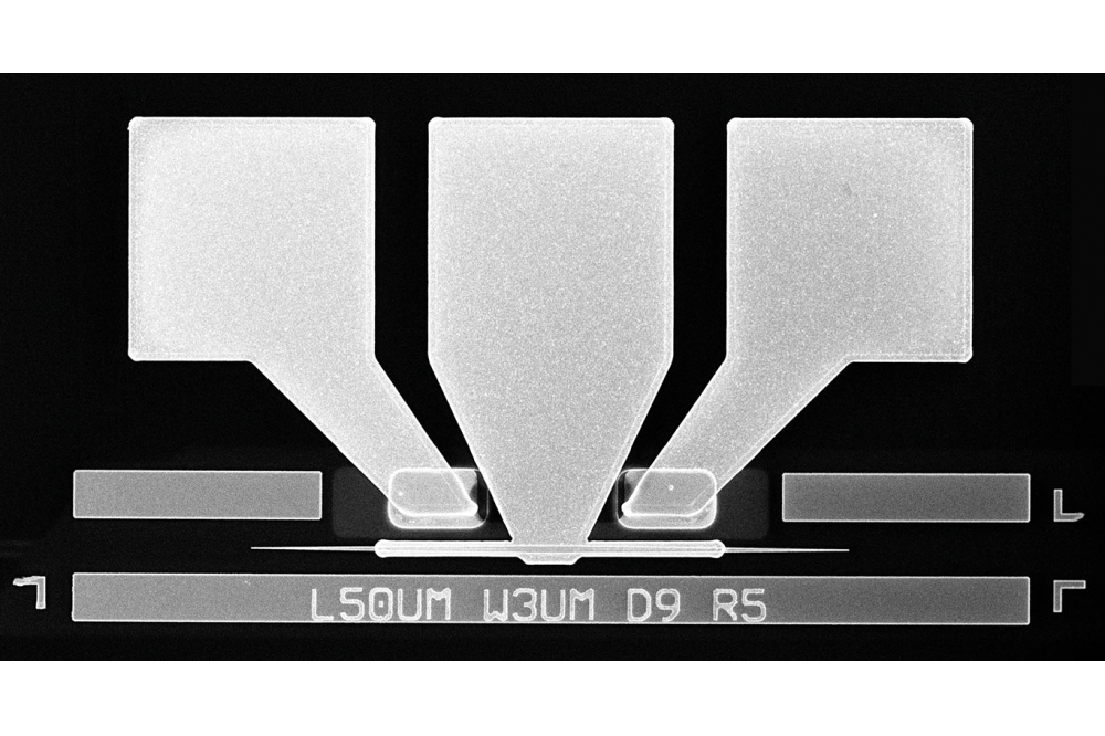
Fig 4: 5x10 mm test chip (left), crossings and TIR-mirrors at the output of a multi-mode interference (MMI) coupler (top right), and Euler bends (bottom right).
The apparent challenge in 3 µm thick SOI waveguides is their highly multi-moded operation. With very careful design and with the support of low propagation losses, it is possible to keep light in the fundamental mode of through-etched strip waveguides. But their rectangular cross-section supports tens of propagating waveguide modes and it is difficult to launch light only to the fundamental mode and to completely avoid the excitation of higher order modes. The solution to this problem was invented already in the 80's when partly-etched rib waveguides were demonstrated to offer single mode operation in almost arbitrarily thick waveguides. Only the fundamental mode can propagate along the rib waveguide, while any other light coupled to the waveguide radiates away into the surrounding Si slab. When combined with an adiabatic rib-strip converter (Fig. 1), this allows to keep light in the fundamental mode, to filter out any unwanted power in the higher-order modes and to make the PICs effectively single-moded. A particularly attractive property of the rib waveguides is that their SM-condition doesn't depend on the wavelength, so that the PICs can be made to have SM operation and low-loss over an extremely wide wavelength range. Some simple waveguide components, such as waveguide spirals, mirrors, bends and wavelength (de)multiplexers have been demonstrated to operate with low loss from 1.2 to >2.4 µm wavelength.
Numerous passive and active waveguide components have been developed and monolithically integrated on the 3 µm SOI platform. These include multi-mode interference couplers, arrayed waveguide gratings, (AWGs), echelle gratings, thermo-optic and plasma dispersion modulators, and Ge photodetectors, just to name a few. Instead of describing them in detail, we focus here on the broadband and polarization independent operation of the platform and its input/output interfaces. As was explained above, the ultra-high mode confinement allows the waveguides and many waveguide components to operate over ultra-wide wavelength ranges. Bends, mirrors, crossings, directional couplers, AWGs and echelle gratings can have >1 µm bandwidth. The last three on this list are interferometric components that have natural wavelength dependency that is used to make e.g. wavelength filtering or (de)multiplexing, but their insertion loss remains small over this ultra-wide bandwidth. In contrast to those, the widely used multi-mode interference (MMI) couplers have a finite bandwidth of ~100 nm, which must be taken into account.

Fig. 5: Horizontal fiber-coupling concept using a polished 12 µm SOI interposer.
Light can be coupled into (or from) the 3 µm SOI waveguides either horizontally or vertically. The former is achieved by simply leaving an etched waveguide facet at the edge of the chip and coating it with an anti-reflection coating (ARC) to reduce back-reflections. A lensed fiber with ~3 µm spot size can be used to couple light to the 3 µm SOI waveguides with very repeatable ~0.5 dB coupling loss. The bandwidth of the fiber-coupling is mainly limited by the fiber itself and the ARC. With a single-layer ARC the low-loss coupling bandwidth is ~100 nm and it can be extended beyond 300 nm by using a multi-layer ARC. Permanent coupling to a standard single-mode fiber array (SSMF) can be achieved with a polished interposer made from 12 µm SOI waveguides (Fig. 5). It connects the SSMF array to a 12 µm thick SOI waveguide array, gradually reduces the thickness of the waveguides down to 3 µm and then couples the light to the 3 µm thick SOI waveguides on the actual PIC chip. Horizontal coupling has also been used to hybrid integrate semiconductor optical amplifiers (SOAs), lasers and modulators on SOI using flip-chip bonding.
Vertical I/O coupling is possible with so-called up-reflecting mirrors (URMs). Those have a wet-etched negative 45° TIR mirror that reflects light up/down through an ARC that is deposited on top of the URM. This has been demonstrated to have as low coupling loss as the horizontal coupling [3]. Vertical coupling can be used for wafer-level testing (WLT), permanent fiber coupling (with suitable fiber arrays or down-reflecting coupling blocks) and hybrid integration. In particular, photodetectors (PDs) and vertical-cavity surface-emitting lasers (VCSELs) have been successfully integrated on 3 µm SOI using URMs.
In conclusion, 3 µm SOI waveguide PICs feature ultra-high mode confinement into the Si core, which enables ultra-broadband, low-loss and polarization-independent operation, as well as dense integration. This makes the technology particularly useful for applications like lidars, spectroscopy and broadband communication.
1] Yisbel Marin, Arijit Bera, Matteo Cherchi and Timo Aalto, "Ultra-High-Q Racetrack Resonators on Thick SOI Platform through Hydrogen Annealing Smoothing," Journal of Lightwave Technology 41 (11), pp. 3642-3648, https://doi.org/10.1109/JLT.2023.3262413, 2023].
2] Matteo Cherchi, Sami Ylinen, Mikko Harjanne, Markku Kapulainen, and Timo Aalto, "Dramatic size reduction of waveguide bends on a micron-scale silicon photonic platform", Optics Express 21 (15), pp. 17814-17823, https://doi.org/10.1364/OE.21.017814, 2013].
3]Timo Aalto, Matteo Cherchi, Mikko Harjanne, Srivathsa Bhat, Päivi Heimala, Fei Sun, Markku Kapulainen, Tomi Hassinen and Tapani Vehmas, "Open-access 3-μm SOI waveguide platform for dense photonic integrated circuits", IEEE Journal of Selected Topics in Quantum Electronics 25 (5), September/October 2019, 8201109, https://doi.org/10.1109/JSTQE.2019.2908551, 2019].