Silicon PIC integration for 100G interconnects on the road to 400G

Radha
Nagarajan, CTO, Optical Interconnect, Inphi Corporation explains
The growing bandwidth demands of cloud service providers (CSPs,) offering a variety of web-based, commercial and consumer services, have in turn driven the demand for higher and higher speed optical solutions to connect switches and routers at the different tiers of the CSP’s data center network. Today, this requires solutions at 100Gbit/s within and interconnecting datacenters. As the demand grows further, Moore’s law dictates that advances in switching silicon will enable switch and router platforms to maintain switch chip radix parity, while increasing capacity per port. As servers (lowest rungs of the datacenter) with 50Gbit/s ports are being considered for deployment, the next generation of switch chips are all targeting per-port capacities of 400Gbit/s. This in turn is driving the need for 400Gbit/s optical interconnects. Here, we focus on the application of Silicon photonics for the implementation of the current generation 100Gbit/s interconnects between datacenters and briefly discuss the path to 400Gbit/s.
How are Datacenters Connected?
The common notion of datacenters pictures them as large, fixed physical locations that are limited in land area. The reality is that interconnected, individual sites are geographically diverse and the optical interconnects between them could span anywhere from few kilometers of terrestrial distances to thousands of kilometers across subsea routes. Optical transmission distances of more than 2 kilometers are the inter-datacenter interconnects (DCI), external to the physical datacenter. Let us consider the three primary types of DCIs.

Fig. 1 -- Commonly used nomenclature for the various types of DCI reaches
DCI-Campus
These connect datacenters which are close together, as in a campus environment. The distances are typically limited to 2km-5km. There is an overlap of CWDM and DWDM links over these distances, depending on fiber availability in the environment.
DCI-Edge
The reaches for this category range from 2km to 120km. These are generally latency limited and used to connect regional, distributed datacenters.
DCI-Metro/Long Haul
The DCI-Metro and DCI-Long Haul, as a group, lumps fiber distances beyond the DCI-Edge up to 3000km, for terrestrial links, and longer for subsea fiber. Coherent modulation format is used for these, and the modulation type may be different for the different distances.
Direct detection and coherent are the choices of optical technology for the DCI (category 2). Both are implemented using the DWDM transmission format in the C-band, 192 THz to 196 THz window, of the optical fiber. Direct detection modulation formats are amplitude modulated, have simpler detection schemes, consume lower power, cost less, and in most cases, need external dispersion compensation.
Coherent modulation formats are amplitude and phase modulated, need a local oscillator laser for detection, sophisticated digital signal processing, consume more power, have a longer reach and are more expensive.
For 100Gbit/s, a 4 level Pulse Amplitude Modulation (PAM4), direct detection format is a cost-effective solution for DCI Edge applications. PAM4 modulation format has twice the capacity of the traditional NRZ format. For the next generation 400Gbit/s (per wavelength) DCI systems, 60GBaud, 16 QAM, coherent format is the leading contender.
Switch Pluggable 100Gbit/s PAM4 DWDM Module
The switch pluggable QSFP28 module (SFF-8665 MSA compatible) is based on a highly integrated, silicon photonics optical chip and a PAM4 ASIC as shown in Figure 2. The four, KR4 encoded 25.78125Gbit/s inputs are first stripped of their host FEC (KR4). Then the two, 25Gbit/s streams are combined into a single PAM4 stream and a more powerful line FEC called IFEC is added, making the line rate 28.125GBaud per wavelength. The 4, 25Gbit/s Ethernet streams are thus converted to 2, 28.125GBaud PAM4 optical streams.
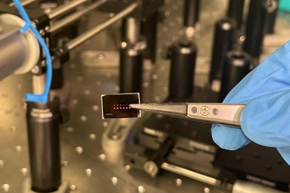
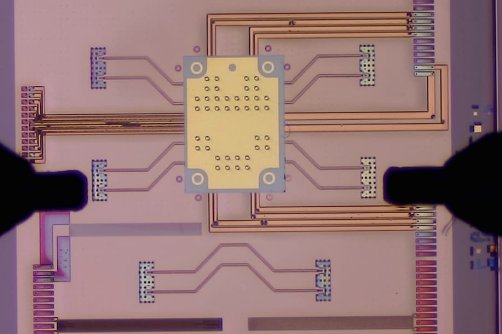
A highly integrated Si photonics chip is at the optical heart of the pluggable module. Compared to indium phosphide (InP), the silicon CMOS platform allows a foundry level access to the optical component technology at much larger 200mm and 300mm wafer sizes. The photodetectors for the 1300nm and 1550nm wavelength range are built by adding germanium (Ge) epitaxy to the standard silicon CMOS platform. Further, Silica and Silicon Nitride based components may be integrated to fabricate low index contrast and temperature insensitive optical components.

Fig 2 -- A 100Gbit/s, QSFP-28, DWDM module architecture
In Figure 2 the output optical path of the Si photonics chip contains a pair of traveling wave Mach Zehnder modulators (MZM), one for each wavelength. The two wavelength outputs are then combined on-chip using an integrated 2:1 interleaver which functions as the DWDM multiplexer. The same Si MZM may be used for both NRZ and PAM4 modulation formats, with different drive signals.
There are a pair of integrated high-speed Ge photodetectors (PD) in the receive path. The dual wavelength receive signal is separated using a de-interleaver structure which is similar to the one used in the transmitter. Since the polarization state of the incoming optical signal is not deterministic, the receive path is designed to be polarization diverse to eliminate polarization induced signal fading. This is accomplished by using a low loss polarization beam splitter (PBS), also integrated onto the silicon photonics chip. After the PBS, transverse electric (TE) and transverse magnetic (TM) paths are processed independently, and then combined again at the PDs. The DFB lasers are external, and edge coupled to the silicon photonics (SiP) chip. Both the MZM driver amplifier and the PD transimpedance amplifier are wire bonded to the SiP chip. We use a direct coupled MZM differential driver configuration to minimize electrical power consumption.
The PAM4 ASIC is the electrical heart of the module. The ASIC supports a dual wavelength 100Gbit/s mode (with 4 x 25Gbit/s inputs), and a single wavelength 40Gbit/s mode (with 4 x 10Gbit/s inputs). The ASIC has MDIO and I2C management interfaces for diagnostics and device configuration.
For a simple point to point transmission system, with two EDFA’s, the ultimate transmission distance is limited by the launch power at the transmitter. We have demonstrated a PAM4 link in standard SMF (single mode fiber) up to 120km for a total fiber loss of 26.2dB.
The DCI-Campus and Edge link configurations are shown in Figure 3. A DCI-Edge configuration has two EDFA’s and a DCM (dispersion compensation module,) which may be part of the mid-stage of the transmit or the receiver EDFA. A DCI-Campus configuration can operate off a single receive EDFA without any external dispersion compensation, since the intrinsic dispersion tolerance of ±100ps/nm is sufficient for this distance. The inset to the bottom, shows the optical spectrum for a fully loaded 40 channel system for a maximum of 4Tbit/s capacity in a fiber pair. The rack to the left, shows an Arista 7504 chassis switch with 36 QSFP28 ports, fully loaded. A single blade of the switch can support 3.6Tbit/s of traffic in any one direction.

Fig. 3 -- Typical switch and line system configuration for DCI-Campus/Edge
Evolution to Switch Pluggable 400Gbit/s DWDM Module
As bandwidth demands in data center networks continue to grow, Moore’s law dictates that advances in switching silicon will enable switch and router platforms to maintain switch chip radix parity while increasing capacities per port. At the time of this manuscript’s writing, the next generation of switch chips are all targeting per-port capacities of 400G. Accordingly, work has begun to ensure the optical ecosystem timelines coincide with the availability of next-gen switches and routers. Toward this end, a project has been initiated in the Optical Internetworking Forum (OIF), currently termed 400ZR, to standardize next-gen optical DCI solutions and create a vendor-diverse optical ecosystem. The concept is in principle like that of the DWDM PAM4 technology described here, but scaled up to support 400Gbit/s requirements.


