Emerging applications: PICs as a platform for lab on chip devices

What does it take to configure photonic integrated circuits for
environmental analysis or biological sensing? Sascha Geidel and Thomas
Otto from Fraunhofer ENAS run through the process step by step by
considering a photonic biosensor for space application (PBSA) and look
at ways of increasing the applicability of optical chips to these growth
markets.
Photonic Integrated Circuits (PICs) can be used for sensing applications like environmental analysis or biological sensing [1]. The applications can be distinguished between reusable and disposable applications. The sample and the reagents necessary for a certain sensing task can lead to an alteration of the fluidic system and the sensor itself. To eliminate a possible cross-contamination between different samples and a decrease in the sensitivity of the sensor, disposable combinations of sensors and fluidics are preferred, especially with biological applications.
Lab on chip (LOC) devices combine certain laboratory processes to achieve an automation of a sensing protocol. The LOCs are employed at the Point of Care (POC), which is highly application dependent and could be at a hospital, a doctor's office or in a remote area. Typically, LOCs are developed to allow diagnostics outside a central laboratory by the automation of manual handling steps like the mixing, filtering and heating of a number of liquids. The LOCs focused on in this article are composed out of a biosensor, a certain fluidic circuit, reagents and actuation mechanisms to allow the controlled manipulation of the liquids.
The ideal LOC for biological applications uses a biosensor that is small, but delivers a broad range of information with a high sensitivity, selectivity and robustness. The lock-and-key principle uses capture molecules, which selectively bind to the target. If there is an array of different capture molecules on a substrate, the system is called multiplex. A typical sensor of that type uses a substrate (e.g. glass, polymer etc.), which is bio-functionalized with, for example, 82 spots in the form of nine rows and nine columns shaped as circular spots with a diameter of, for example, 200 µm and a spacing of 500 µm. The sensor is positioned on a channel with the active area of the sensor facing towards the liquid within the channel. Selectivity and dimensions of the array are mainly affected by the biochemical procedure (so called assay) and the technological capabilities to functionalize the sensing areas. Sensitivity and robustness are mainly influenced by the sensor system underneath the biological layer.
Biosensors for mobile applications feature the capability of being potentially highly miniaturize-able. The used liquids are typically in the microliter range, despite very rare targets within a sample liquid (e.g. blood, saliva), where pre-concentration steps need to be applied. Once the sensor has been implemented, the remaining elements of a disposable LOC, the microfluidic channel network and the actuation mechanisms, become the focus of the miniaturization.
The microfluidic channel network can be produced out of polymer materials. Metals and glass are not preferable since they are too expensive for disposable applications [2]. The most famous material for microfluidic prototypes, when looking at research papers, is the silicone Polydimethylsiloxane (PDMS). It is easy to use for the casting of microfluidic structures but also comes along with some drawbacks, which excludes it from close-to-market, low-cost applications [3]. Therefore, it is recommended to transfer microfluidic networks to well-known, state of the art technologies like standard injection molding as soon as possible.
When it comes to additional actuation functionality, the same boundary conditions with respect to the microfluidic channel network have to be taken into account. Among other technologies, the electrochemical actuation technology developed by Fraunhofer ENAS shows unique features with respect to size, cost and integrability [4], [5], [6], [7].
This article illustrates how photonic integrated circuits can be transformed into a LOC system by considering the project Photonic Biosensor for Space Application (PBSA) funded by the EU, which focuses on the integration of microfluidic actuation, a photonic sensor and the bio-functionalization as well as the biochemical protocol into one LOC. The whole system was meant to be included in a small enclosure, which carries all necessary supporting infrastructure to drive the LOC. The target application was to analyse extraterrestrial soil for traces of life in terms of biological targets. State of the art analysis uses spectroscopic approaches, which list up elements present in the sample. The detection of bacteria or enzymes relies on wet chemistry approaches, which aren't available for space yet [8"“10]. #
Modifying the PIC for biosensing
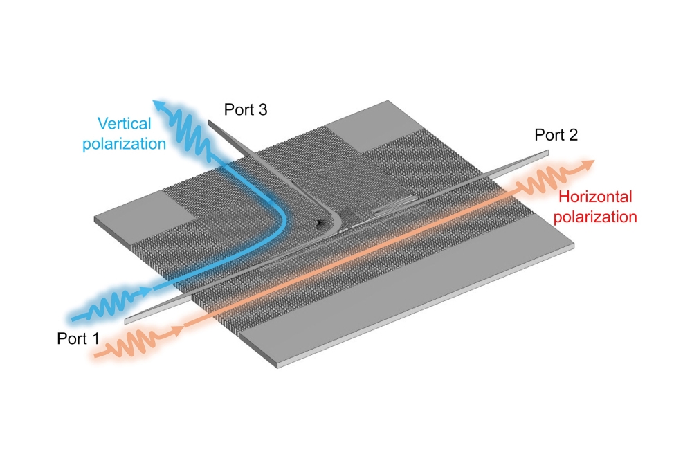
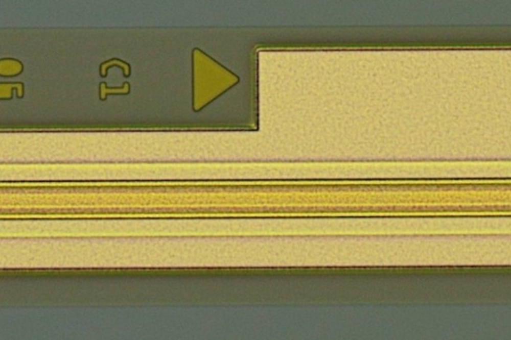
The PIC has an outer dimension of 9.5mm square and was developed by DAS Photonics, Spain. It combines a light input port with optical ring resonators and an optoelectrical interface (Figure 1a). Figure 1b shows the PIC's layout and marks certain important areas, which will be described further on. Starting at the bottom left corner of the scheme, the light enters the chip through optical couplers ("Light Input Port with Grating Couplers") and is guided through waveguides ("Waveguide") to the sensor areas of the chip. To achieve a multiplex sensor, the signals are split into an array of multiple sensor elements called optical ring resonators (the blue underlain area on the right; "Optical Ring Resonator"). Outgoing optical signals are transformed to electrical signals ("Light-To-Electrical Signal Interface") by integrated photodiodes ("Photodiodes"). The collected electrical signals are transported through bonded wires ("Electrical Output Port") to a signal amplification and interpretation electronic within the electronic management system.
The reagents and the sample get pumped over the surface of the PIC along with the "Sample Flow Channel" (figure 1b). Around this area, a sealing will ensure the leakage free progress. The necessity of a sealing demands a certain increase in the dimension of the PIC. The optical ring resonators are not covered with an oxide and can interact with the stream of chemicals within the sample flow channels (figure 1 c3). A signal change can be observed during any change of the media. To achieve a selectivity for a specific biosensing application, the ring resonators need a surface treatment and bio-functionalization. 
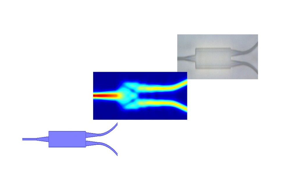
Figure 1: (a) photography of the final PIC; (b) Overall Layout of the (PIC) with the single function areas marked; (c1) Integrated photo diodes for the conversion of the optical signals within the waveguides to electrical signals evaluable by the electronic management system; (c2) Vertical grating coupler to deliver the light (c3) Cross section of the PIC at the optical ring resonators in contrast with the waveguides; (c4) Technical drawing of an optical ring resonator sensing structure; (c5) Layout of a splitter structure with a false-colour simulation of the light distribution.
Bio-functionalization and biochemical procedure
The bio-functionalization is a procedure to bind antibodies to the optical ring resonators which was done by the Centro de Astrobiología (INTA-CSIC), Spain [11]. The antibodies are the major element for the afore mentioned selective key-lock-binding principle of a certain target within a sample. Figure 2a shows a 3D illustration of an optical ring resonator CAD model. On top of the blue substrate, the optical guiding structures are shown. The reddish cuboid represents the liquid flushing over the surface. The Y-shaped, yellow objects are the antibodies, which are commonly represented in that form. The antibodies are bound to the surface by printing small droplets with a certain antibody concentration on the surface after the surface was primed by a sequence of chemicals. The optical ring resonators only sense changes happening within their evanescent field. An immobilization of antibodies outside this field would lead to not detectable binding events and to a certain decrease in the concentration of the target within the sample. In conclusion, the sensor will have a lower sensitivity in comparison to the potential sensitivity the PIC is capable to deliver [12].
The biochemical procedure on one fully functionalized ring resonator is as follows. First, a buffer solution gets pumped over the ring. The shift in the resonance frequency of the ring is transformed into the first signal level increase as shown in figure 2-b1. The sample solution typically comes with a variety of different, potential biological targets. As soon as this mixture arrives at the sensing elements, a diffusion based, selective binding of the target within the sample to the immobilized antibody occurs (figure 2-b2). After the sample volume got pumped over the surface of the sensor, a washing step follows, which washes away all compartments, which have not bound to the antibodies (figure 2-b3). If the sensitivity of the sensing element and the amount of target within the sample, which has bound to the antibodies leads to a sufficient amount of signal increase, additional steps are not necessary. The biochemical assay would, in this case, be called label-free. To enhance the signal of the sensor, additional compartments can be bound to the target on the rings. This could be a secondary antibody (figure 2-b4 and 5) and for example an additional nanoparticle (figure 2-b6 and 7).

Figure 2: (a) 3D CAD illustration of Biosensor; (b) Schematic of the signal progression of one bio-functionalized optical ring resonator and a description of the procedure within the biochemical layer
Assay miniaturization and sensor integration
With the functionalized sensor, the detection system is ready, but relies on personnel to manually pipette the liquids on top of the surface of the sensor, step by step. A microfluidic cartridge can work as a passive interface for the liquids from an external reservoir to the sensor as depicted in figure 3. The fluidic cartridge is composed out of a milled polymer chip, which guides the liquid from certain tube ports to the PIC's sensitive area (figure 3a). The connection is made by clamping to allow a reuse of the PIC for this prototyping stage. The system relies on external pumping actuation with external reagent reservoirs. The PIC is placed on a PCB and connected to it by bond wires. An optical fibre connects to the optical couplers on the PIC and an amplifier circuit collects the electrical signals to track the resonance shift of the different optical ring resonators (figure 3b). Such a setup can be used to validate the interface of the fluidics to the sensor and to experiment with volumes and flow characteristics of the single process steps for assay transfer reasons.

Figure 3: Fluidic Integration Step 1: (a) CAD design of a fluidic cartridge without integrated actuation but with a fluidic interface to the PIC sensor. The liquid path is marked with blue arrows; (b) Photography of the laboratory setup that combines the fluidics with the PIC and the PIC with the photonic input and electric output
The necessity of external actuation and reservoirs decreases (besides other drawbacks) the user friendliness. Systems which want to be used by customers outside a laboratory, especially used by medically unskilled personnel, need to integrate actuation mechanisms. Eventually, the user only needs to put disposable cartridges into a reader after loading the cartridge with the sample. No additional handling besides the plug & play -nature of the cartridge exchange should be carried out. The microfluidic cartridge technology developed at Fraunhofer ENAS, Germany is capable of storing different liquids in certain cavities within a polymer part. The twist behind this technology is the integrated actuation principle, which is highly miniaturized to allow each individual liquid reservoir to be equipped with its own pump.
Preliminary to the application specific cartridge design, an intermediate prototype was developed. This prototype is composed out of the photonic sensor together with a standard cartridge called flex.flow microscope slide, which is commercially available and was kindly provided by BiFlow Systems GmbH, Germany (figure 4a). The flex.flow cartridge relies on the afore mentioned actuation technology, is not application specific and can be purchased as an evaluation kit. The cartridge does not include a biosensor but allows developers of biosensors to combine their sensor with a cartridge, which actually makes it a Lab-on-Chip device already. The port for the sensor is simply designed as two holes on top of the cartridge (the holes are positioned within the red frame of figure 4a). The first hole allows liquids to get pumped from internal reservoirs to the sensor. The second hole guides the liquid from the sensor to a waste reservoir. The holes on the cartridge have a certain distance, which is bigger than the PIC itself. To bridge this, the sensor was embedded into a stack of polymer sheets. This stack guides the liquids over the surface of the sensor (figure 4b; blue arrows). To verify the proper functioning, an experiment was done without a bio-functionalization of the PIC. Four different concentrations of the buffer solution PBS were used. Each liquid was placed into a different reservoir of the combined cartridge-sensor prototype (figure 4c). The evaluation kit uses a small power source and a plugging port (comparable to a USB port) to drive each individual pump on the disposable cartridge. The cartridge was programmed to pump the different concentration over the surface of the PIC one after another and the response of the sensor was recorded (figure 4d). The sensor was able to track the different concentrations.

Figure 4: Fluidic Integration Step 2: (a) Photography of a standard microfluidic cartridge with integrated pumping capability; (b) Customized plastic component to combine the PIC with the cartridge; (c) Photography of the prototype that combines the cartridge with the PIC; (d) Experiment result showing a simple measurement of different concentrations of a buffer solution done by the prototype.
The cartridge used here is a standard system from BiFlow Systems. It is versatile enough to be combined with different sensor systems and to drive an amount of liquids. Since it is not specially designed for one purpose, volumes and assay steps are limited. Each assay is different and therefore, a miniaturization and transfer to the microfluidic cartridge has to be done. Both prototypes were used to validate all necessary assay steps and the bio-functionalization. Concentrations, flow velocities and volumes were analysed and the results were used for a specialized cartridge design.
The design allocates each assay step (or rather each liquid getting pumped) to an individual reservoir and pump. Elements were included that trace back to the experiences made with the integration of the PIC into the prototypes. Further on, the cartridge was extended by fluidic connection and a valving system that allows an external robot to fill samples into the cartridge in an automized or remote control manner. As a boundary condition of the projects target mission, enough functions were integrated to allow storage and processing of two consecutive assays to be performed (figure 5).

Figure 5: Specialized cartridge for the PBSA system including PIC interface, tailored sample input system, multi-assay layout and mechanical and electrical interfaces, which allows a system integration into a support and control box.
PBSA system overview
All necessary components for the control of the cartridge and the sensor were combined into a single enclosure. The system level design was made by Evoleo Technologies, who are expert payload developers and satellite integrators for space applications. Radiation hardened and mechanically durable components and designs were used to fulfil the project's requirements for the demonstrator. The top three layers provide typical, necessary support components as well as an electronic control system including an operating system and the control algorithms for the microfluidic cartridges (figure 6a and b). The two layers on the bottom provide the PIC with an optical input signal and a read-out of the sensor signal. The laser component has an additional mechanical guiding structure on top to allow a proper integration of the fibre into the enclosure and a proper alignment to the PIC. The middle layer of the system is the microfluidic cartridge in combination with the PIC known from figure 5.
The operability of the system was shown within the project. The different reagents for the assay were preloaded into the cartridge, the cartridge was closed and in combination with the PIC included into the enclosure. After the sample was loaded into the system through the tube connectors on the bottom of the enclosure, the automatic detection procedure was started. The liquids got pumped over the sensor and the sensor's response was recorded. The target within the sample was measured selectively but with a low sensitivity in comparison with prior experiments in the laboratory. Some of the experiments were already published open source [13].

Figure 6: System level integration. (a) Schematic of the different boards and systems that are necessary for an independent system; (b) photograph of the final demonstrator for the project.
Summing up
Lab on chip devices can be composed of a varying set of actuation and sensor principles. The focus of this article was to describe how a photonic integrated circuit can become a biosensor and what has to be done beyond this to develop a Lab on Chip device. The application scenario was the project PBSA, where a system for biochemical analysis on the basis of wet chemistry was developed that is potentially capable of performing analysis in a harsh and remote area on earth or during planetary exploration missions.
Applications, where it is necessary to specifically bind a target to achieve a significant result, rely on disposable, sensing system, as long as a total (biochemical) reconditioning of the system can't be guaranteed. This leads to the question of exchangeability of the consumed parts after each measurement. The PBSA system was based on the mission scenario, where the instrument is a payload of an autonomous rover. For the project it was stated to be easier to equip the rover with multiple instruments instead of a manipulator for the exchange, aligning and fixation of the LoC within the instrument. At this point, there is no final answer to the question of exchangeability for remote applications of LoCs. But for typical human or veterinary diagnostic applications, exchangeability has to be implemented into every product development.
Future thoughts
In general, the applicability of PIC's for Lab on chip systems can be increased especially by the optimization of three parameters of the sensor: One-time usage, connectivity and necessary supporting systems. One-time usage is high with a sensor that uses cheap materials. A material mix analysis done by Yole Développement within the study on "Microfluidic Applications 2015" ([2], pg. 42) showed that the disposable segments (Clinical & Veterinary diagnostics, Point of Care diagnostics) use silicon in only 1 to 6 percent of the application cases but polymers in between 77 to 87 percent. Silicon based biosensors would increase their importance for the Point of Care market by transferring their technologies to polymer materials. In 2013 Hu et al. published a paper on the fabrication of photonic structures on flexible foils [14]. Photonic sensors based on such technologies could be manufactured in a roll to roll manner leading to an enormous scaling effect on production cost, which would also increase the one-time usability and the applicability of Lab on a Chip systems. The alignment of a fibre or a fibre array to the PIC is an element, which should be simplified for an easy exchange of the LoC after use. A plug & play solution would increase the user friendliness of the system. The necessity of a laser as an infrastructure component for the sensor reduces the mobility of a PIC-based Lab on Chip instrument. Especially looking at competing sensor technologies like electrochemical or fluorescence based technologies, PICs have to argue about their unique selling proposition.
PICs have unique features, but there are competing technologies, which are also suitable for biosensing applications. At this point, there is no killer application or technology which will exclude PICs as biosensor principles for point of care tests. The first one, who occupies important niches or applications, will make it harder for other players to enter the market. But we also see a broad range of different providers of point of care tests working in the same application field nowadays, especially with rapid home glucose test systems. This is an application where the commercial spread is extremely low because of the low price of each test strip. It is surprising that there doesn't seem to be a displacement but a growing market here. The applications, which will use an active fluid control on the disposable system, will have higher prices and need to provide solutions for more complex, diagnostic protocols, where lateral flow strips can't be applied. For example - DNA analysis, rare target samples, bio markers with high similarity, assays with the necessity of sample preparation and all multi-marker and quantitative tests. These boundary conditions can be provided by some technology combinations including PICs. The future will show, which one will be the first on the market. But we are sure that we will have a highly diversified market of LOC's with different technology combinations existing in parallel in the future.