Photonic integration: a step-by-step guide
What does it take to go from idea to final device? Iñigo Artundo, CEO of VLC Photonics, introduces the process and prepares you for the journey.
As a starting point, let's say that you are aware of photonic integrated circuits, and have an idea of the optical system that you would like to embed into a chip. It's now time to think about the many questions you'll have to answer and the many choices it will be necessary to make even before you get started designing the chip. In this article, we will explore these, shedding light on the sometimes overwhelming technology of photonic integration.

Figure 1. The main development stages of a photonic integrated circuit stand over small but important choices.
Why: Reasons for (photonic) integration
The first stage in the thinking required, will be to clarify what is the most important reason to get an optical system integrated monolithically on a photonic chip, as this will shape many of the choices ahead. The reasoning here follows the same line as with the 30-years-more-mature electronic integration technology, but it is still fully applicable to photonic integrated circuits.
The first reason can be the need for a reduction in size and weight, which is critical for some applications "“ for example, in aerospace, where every millimeter and every gram counts. Also, for some mobile sensing applications, devices need to be small enough to fit into a hand-held unit. In this case, an assembly of discrete optical components might be too bulky or heavy, due to redundant packaging and interconnects between several devices.
A second reason can be in order to scale up production to huge volumes, just like in electronics, where chips can be produced by the millions for use in popular consumer devices or in automotive applications. Not all optical systems can easily scale up to serve certain markets, especially if the scalability of their individual components is not the same. Any optical system that requires an assembly of several discrete components will surely be a challenge when aiming at mass volumes with high yield.
Another reason can be the need for robustness. Having a system monolithically embedded into the same substrate makes it much more resistant versus vibration, shock, humidity or radiation, and easier to stabilise with respect to changes in temperature. Such features can be critical for ruggedised or industrial environments.
Cost is always an important factor too. Once a chip has been developed, the costs of mass manufacturing it are negligible in comparison, which allow device-makers to achieve economies of scale that are not possible with products based on more complex assemblies. Such cost advantage is critical for some mature optical markets like fibre telecom, although the concept of high volume might not be the same for other markets, and a 1000 units/year production of a high added value circuit can still be profitable.
And finally, integration can allow for greater complexity of the embedded systems, in other words, the possibility of proposing completely new optical architectures with hundreds or even thousands of optical components on a photonic chip, something completely unthinkable with discrete assemblies. Sometimes, some functionalities can only be implemented on an integrated way, also opening the doors to new devices that were not available off the shelf.
Where: The quest for the best substrate
The first step will be to have a clear definition of the optical system you want to integrate. This means a high-level specification of the basic functionalities required "“ for example, a fibre telecom transmission system composed of a laser source, a modulator and a multiplexer, or a medical diagnostic system composed of light couplers and some resonating structures for sensing. On a high level, this will allow us to make the first choice on where we want to place our design: the substrate material and integration platform.
Unlike in electronics with silicon, in photonics there is not a predominant substrate material (yet), and several platforms have evolved along the years, each of them excelling at different features:
Silicon photonics: (also referred as silicon-on-insulator, or SOI): extremely compact and scalable to large production volumes (and thus low cost per die), compatible with electronics on the same substrate;
Indium Phosphide (InP): the only platform allowing for monolithic generation and amplification of light;
Silica (SiO2, also known as Planar Lightwave Circuits, PLC): the lowest propagation and fibre coupling losses, over mature and low cost fabrication platforms;
Lithium Niobate (LiNbO3): excellent electro-optic effect for modulators;
Silicon Nitride (Si3N4): compact and low loss material, with operation in the visible wavelength range.
Which: Mapping devices into building blocks
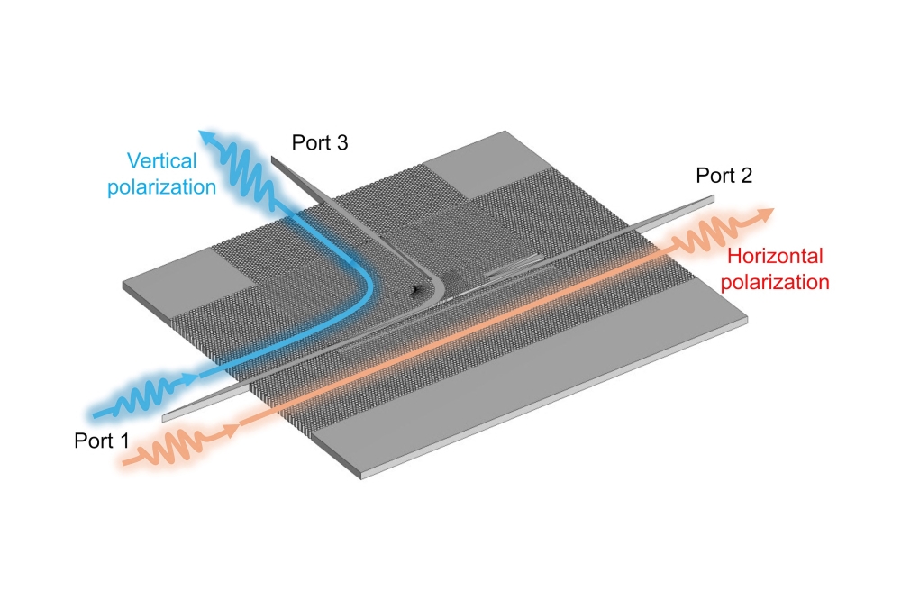
The system functionalities will need to be mapped to specific devices under the selected integration substrate, and moreover, each device will then need to be specified as much as possible, as this will help determine the optimal foundry platform. To give an example - a wavelength multiplexer or filter functionality can be implemented by several devices such as an Arrayed Waveguide Grating, an Echelle Grating or cascaded Mach-Zehnder Interferometers. Each of these devices will have different performances under different integration substrates and platforms, and a careful evaluation of the trade-offs and selection of the optimal development path is critical for long term success.
Once an implementation of the system with specific devices under a certain material platform has been selected, it is time to transform that information into a circuit design. Each device will be converted into a building block, which can already be found in the Process Design Kit (PDK) of the target manufacturing foundry, or located in a library of a photonic design house, or needs to be designed from scratch. Which building blocks are selected will determine the performance and reliability (yield), depending on their source.
The added value of using pre-existing building blocks is that they save modeling, simulation and design time for external users, and reduce the uncertainty on final device performance and the risk of implementation errors as these approaches have already been validated. Not all foundries provide PDKs, and support may not extend across all design software frameworks. Also, not all building blocks are validated the same way, with some having different maturity levels on their specifications. Hence, the experienced advice of a professional designer on the selection of building blocks and/or customisation can turn out to be very valuable.
How: Laying out the photonic circuit
Finally, the complete optical system needs to be composed into a layout of interconnected building blocks, including not only all devices, but also electrical contact pads, or optical input and output ports. Routing of optical waveguides and metal paths can sometimes be tricky due to thermal and optical crosstalk and losses, especially if high radio frequency signals are routed too. Smart layout techniques are used in order to alleviate this, and also to minimise the size of the overall photonic chip, in order to save space and cost.
Moreover, each foundry will provide a set of design rules such that the design delivered by the user (in GDS format) is compliant for fabrication. Not only that, but certain design rules also need to be accounted for to allow easy packaging and testing, otherwise you may risk very complex and expensive processing afterwards. Once more, the support of a design house on how to best arrange the chip, or to review your own layout, will be paramount in order to achieve optimal performance and a smooth development path in future integration stages.
Finally, after the layout is delivered to the foundry, it only rests waiting for a few months until the chips are back, so they can be characterised and eventually packaged into a working prototype or a product. These are actually the longest and most expensive parts of the integration process, and the investment on the initial evaluation and design stages is insignificant in comparison. But at the end, if the bases set at the start are not right, all future stages (characterisation, manufacturing, packaging, test and qualification) will be in danger. So my advice is that it's better to be safe and make careful and educated choices in the beginning, and get as much expert support as possible on the early stages.

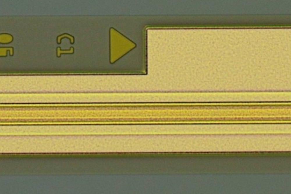
Figure 2. Arrayed Waveguide Gratings on three different platforms (from left to right: SiN, SOI and InP) as designed (top) and manufactured (bottom).